
Device and method for x-ray tube focal spot size and position control

An X-ray tube and focal spot technology, applied in the field of X-ray tube focal spot parameter control, can solve the problems of expensive, non-existent focal spot size, etc., and achieve the effect of avoiding artifacts

Inactive Publication Date: 2009-10-14
KONINKLIJKE PHILIPS ELECTRONICS NV
View PDF1 Cites 8 Cited by
  • Summary
  • Abstract
  • Description
  • Claims
  • Application Information

AI Technical Summary

Problems solved by technology

[0004] However, there is no compensation for changes in focal spot size, so that the control loop may react to erroneous input signals
Another disadvantage of this approach is that it requires expensive equipment that must be designed to be mechanically stable under the G-forces on the CT gantry and that must be frequently calibrated to compensate for the two detectors used in their Differences in Sensitivity and Linearity Accumulated Over Lifetime

Method used


Image

  • Device and method for x-ray tube focal spot size and position control
  • Device and method for x-ray tube focal spot size and position control
  • Device and method for x-ray tube focal spot size and position control

Examples


Embodiment Construction

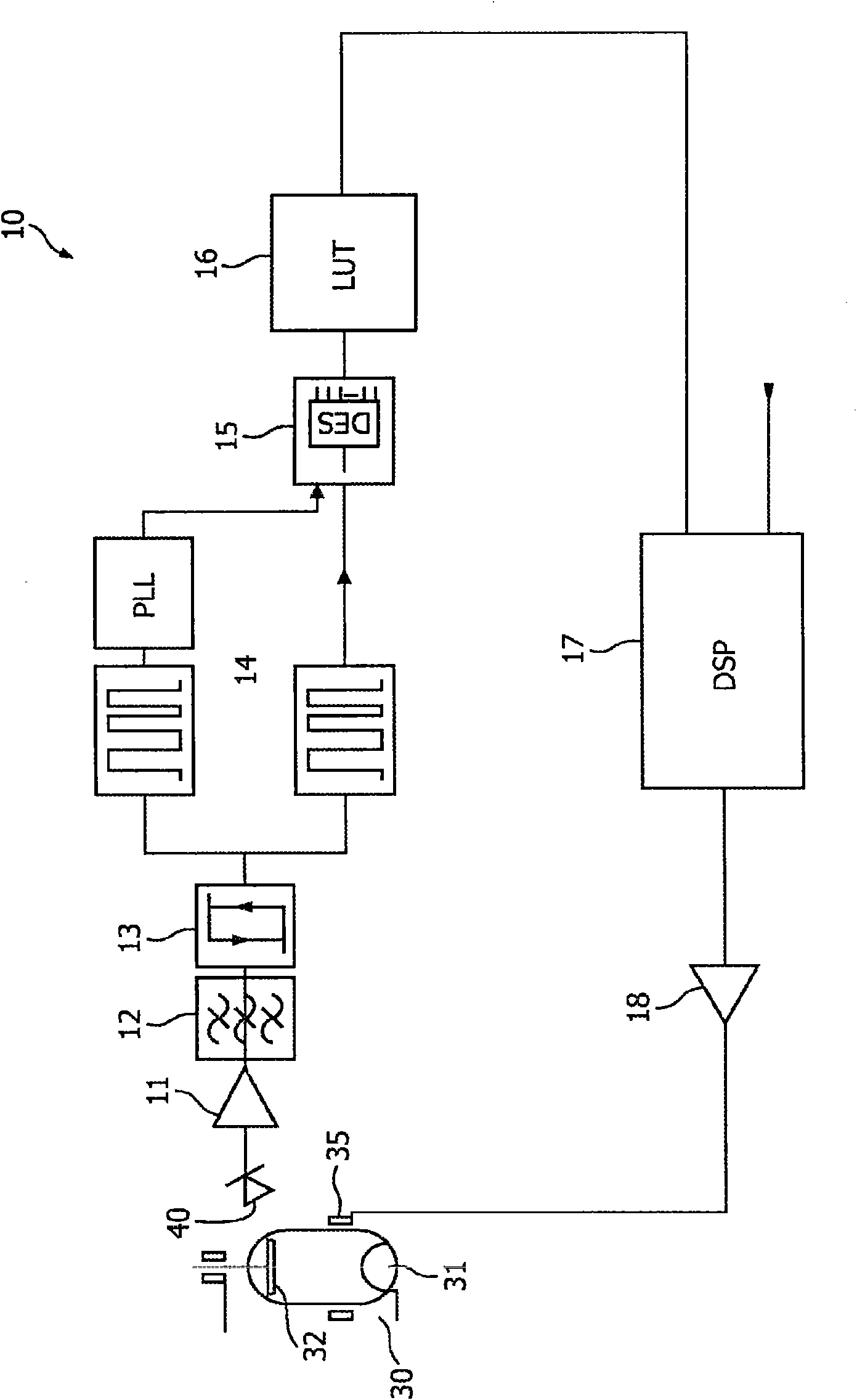
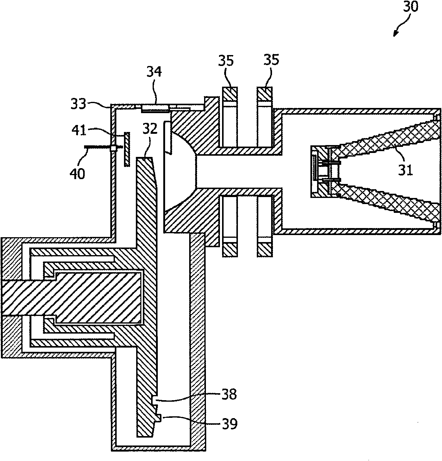
[0041] figure 1 An apparatus for providing control signals to control focal spot parameters of a focal spot on an anode 32 of an X-ray tube is shown. The device comprises an interface 11 for receiving a signal having a characteristic pattern depending on stray electrons detected in the X-ray tube 30 . The X-ray tube is shown for explanatory purposes only and is therefore shown schematically. The X-ray tube comprises an emitter 31 and an anode 32, wherein the emitter is adapted to emit electrons towards the anode. The detection unit 40 is shown outside the X-ray tube 30 for explanatory purposes only, and may also be placed inside the X-ray tube 30, in particular when detecting stray electrons. The X-ray tube also includes a deflection yoke 35 . The interface 11 can be terminal, but can also be equipped with an amplifier for amplifying the received signal. The interface 11 may also include any processing utilities for processing received signals where appropriate. figure 1 ...


PUM


Abstract

A device and method for X-ray tube focal spot parameter control, wherein stray electrons are detected in an X-ray tube. The detected electrons lead to a signal having a characteristic pattern. The characteristic pattern may be evaluated, and based on the evaluation a controlling signal may be outputted so that a fast and exact controlling of the operating parameters of an X-ray tube may be carried out based on the detected stray electrons.

Description

technical field [0001] The present invention relates to a device and method for controlling focal spot parameters of an X-ray tube, in particular, to controlling the size and position of the focal spot based on the detection of stray electrons, so that the state and position of the focal spot can be determined situation, and rapid control of the focal spot can be implemented to improve the efficiency of x-ray tube operation. Background technique [0002] In an X-ray tube, about 40% of the electrons striking the anode are reflected (stray). The number of these stray electrons striking any given area within the X-ray tube varies considerably. The cause may be, for example, a deviation between a focal spot parameter, which may be a focal spot size or a focal spot position, and an optimal focal spot parameter. In many applications of x-ray inspection devices, only very small tolerances can be tolerated without compromising the variation of focal spot parameters such as focal s...

Claims


Application Information

Patent Timeline
Patent Type & Authority Applications(China)
IPC IPC(8): H01J35/14H05G1/52
CPCH01J35/14H05G1/52H01J35/147H01J35/153
Inventor L·科赫W·克罗斯特H·罗洛夫
Owner KONINKLIJKE PHILIPS ELECTRONICS NV
Learn More