
Electric motor stator

A stator and stator core technology, applied in the field of stators, can solve the problems of difficult winding space, winding stuck into the cut-in part, unable to ensure the amount of winding, etc., and achieve the effect of homogeneous winding operation

Active Publication Date: 2009-10-14
MAKITA CORP
View PDF0 Cites 2 Cited by
  • Summary
  • Abstract
  • Description
  • Claims
  • Application Information

AI Technical Summary

Problems solved by technology

[0009] However, if the technology disclosed in the above-mentioned Patent Document 2 is adopted, for example, the pole arc (the part which is provided so as to extend in the circumferential direction from the tip of the magnetic pole teeth and is curved in an arc shape when viewed from the axial direction of the stator) The top end or the ring part of the stator becomes an obstacle when winding, so it is difficult to carry out high-density and high-efficiency winding operations, especially it is difficult to guide the winding to the inside of the winding space
[0010] In addition, if the technology disclosed in the above-mentioned Patent Document 3 is used, if the amount of winding to the magnetic pole teeth is large, when the stator is closed into a circular shape through the cut-in portion for expansion after the winding is completed, Or when the segments are combined into a ring shape, the winding on the outer peripheral side may be caught in the cut-in portion, and a sufficient winding amount commensurate with the winding space may not be secured.

Method used


Image

  • Electric motor stator
  • Electric motor stator
  • Electric motor stator

Examples


Embodiment Construction

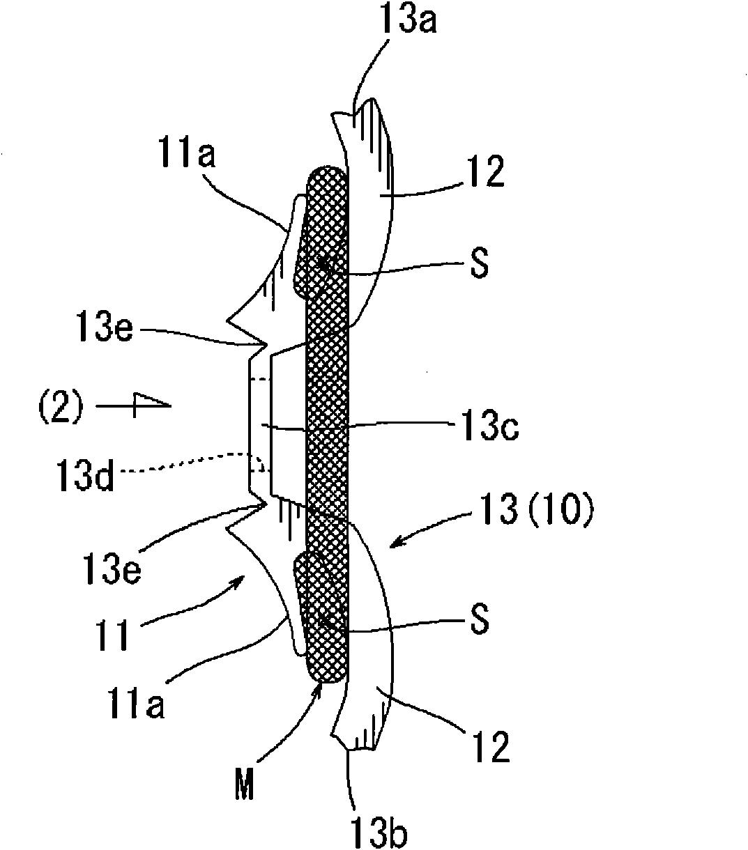
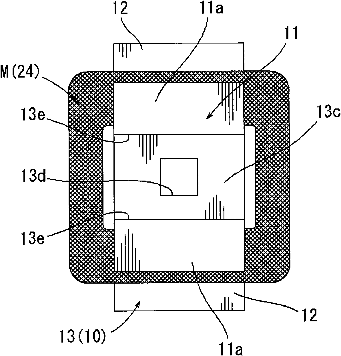
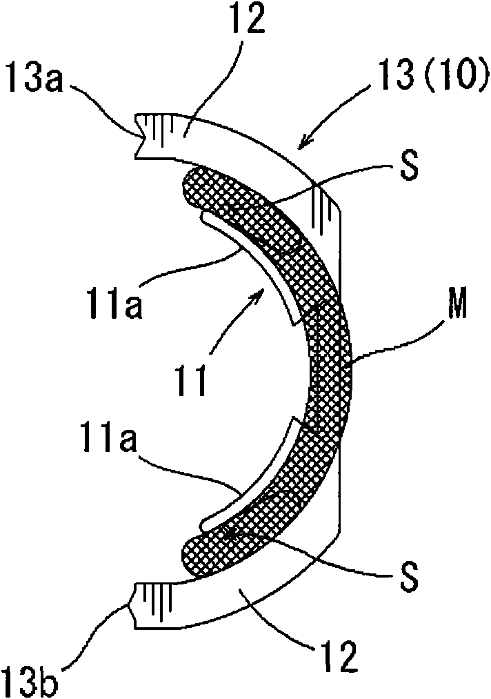
[0040] Below, according to the attached Figure 1-13 Embodiments of the present invention will be described. As one of the examples of the stator of the motor, in the embodiments described below, a two-pole stator in which two magnetic pole teeth face each other is taken as an example. Figure 4 The stator 1 in the first embodiment is shown. The stator core 10 of the stator 1 has a substantially circular shape when viewed from the axial direction of the motor, and a rotor R is provided on the inner peripheral side after the magnetic pole teeth of the stator core 10 are wound. The stator core 10 is formed by laminating a plurality of thin steel plates punched by a punching press to form a whole, and has two magnetic pole teeth 11 facing each other on the inner peripheral side.

[0041] Such as Figure 5 As shown in , the stator core 10 can be divided into two segments (two iron core splits 13) in the approximate center of the ring, and the two magnetic pole teeth 11 are resp...


PUM


Abstract

When winding a wire around the magnetic teeth of a stator core, it is possible to use the conventional technique which spreads the stator core for winding the wire. However, in the case pf two-pole stator, the winding space has a large curvature and it is difficult to perform a sufficient winding. The present invention enables a user to perform a sufficient amount of winding with a high density even in a winding space of a large curvature. Hinge portions (13e) are arranged on the magnetic pole teeth (11) so as to spread pole arcs (11a) toward outer circumference, so that winding is performed in the state that the winding spaces (S) at the both sides of the magnetic pole teeth (11) are positioned in series on a single straight line.

Description

technical field [0001] The present invention relates to a stator (stator) of a motor built in, for example, an electric power tool, and particularly relates to its winding structure. Background technique [0002] Conventionally, techniques described in the following patent documents are known regarding the winding structure of the stator or its magnetic teeth. [0003] In this patent document 1, the following technology is disclosed. The stator is divided into a plurality of segments in the circumferential direction, and each segment contains one or more magnetic pole teeth. After winding each magnetic pole tooth, each The segments are combined with each other to make a circular stator. [0004] Patent Document 2 discloses a technique in which a stator core having a two-pole structure is divided into two parts, and a winding operation is performed on magnetic pole teeth of the two-part cores at the same time, thereby improving the production efficiency thereof. [0005] Pa...

Claims


Application Information

Patent Timeline
Patent Type & Authority Applications(China)
IPC IPC(8): H02K1/18H02K15/095H02K1/16
CPCH02K1/148H02K15/095
Inventor 深津伸一加纳贵纪丸川圭一村濑浩史
Owner MAKITA CORP
Learn More