
Linear fiction welding device

A linear friction welding and equipment technology, applied in welding equipment, non-electric welding equipment, metal processing equipment, etc., can solve the problems that servo valves are difficult to solve, servo valves can only be imported, and welding costs are high, so as to reduce the total flow and benefit The effect of popularization and application and low welding cost

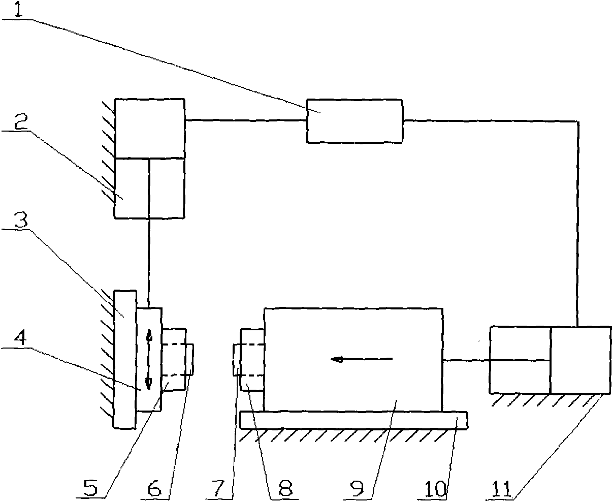
Inactive Publication Date: 2009-10-21
BEIJING AVIATION MFG ENG INST CHINA AVIATION NO 1 GRP
View PDF0 Cites 25 Cited by
  • Summary
  • Abstract
  • Description
  • Claims
  • Application Information

AI Technical Summary

Problems solved by technology

The shortcoming of this linear friction welding equipment is: the first, the servo valve that controls vibration oil cylinder assembly 2 to realize the high-frequency vibration of vibration slide table 4 is difficult to solve
Servo valves that require both high frequency response and large flow rate can only be imported, which is extremely expensive and difficult to maintain
Second, high energy consumption and low efficiency
The power of linear friction welding equipment is as high as hundreds of kilowatts, while the power consumed at the welding joint is only 1 / 20 to 1 / 30, and most of the power is used to overcome the inertial force generated by the vibrating parts, resulting in low efficiency and high welding costs

Method used


Image

  • Linear fiction welding device
  • Linear fiction welding device

Examples


Embodiment Construction

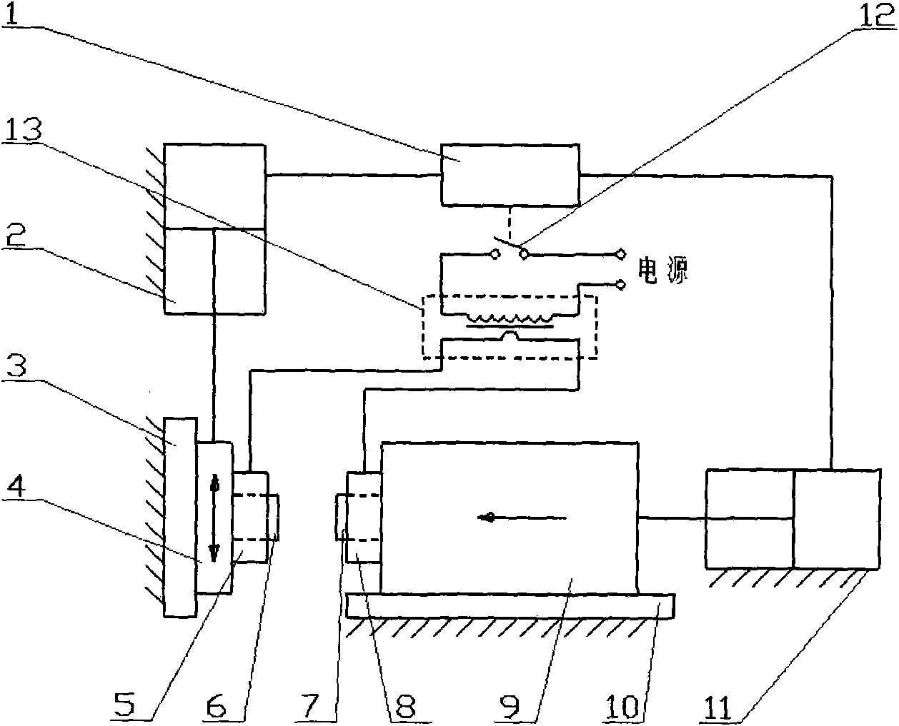
[0012] The present invention will be described in further detail below. see figure 2 , a linear friction welding equipment, which includes a console 1, a vibrating cylinder assembly 2, a vibrating column 3, a vibrating slide table 4, a vibrating end fixture 5, a vibrating end test piece 6, an upsetting end test piece 7, and an upsetting end fixture 8. Upsetting slide table 9, bed 10 and upsetting cylinder assembly 11; vibrating cylinder assembly 2, vibrating column 3 and upsetting cylinder assembly 11 are installed on the bed 10, vibrating slide table 4 and vibrating column 3 pass through guide rails Mechanism connection, the vibrating end fixture 5 is fixed on the vibrating slide table 4, the vibrating end specimen 6 is clamped on the vibrating end fixture 5; the upsetting slide table 9 and the bed 10 are connected by a guide rail mechanism, and the upsetting end fixture 8 is fixed on the On the upsetting slide table 9, the upsetting end test piece 7 is clamped on the upset...


PUM


Abstract

The invention belongs to welding technology, relating to the improvement of a linear fiction welding device, which comprises a control platform (1), a vibration cylinder component (2), a vibration upright post (3), a vibration sliding table (4), a vibration end fixture (5), a vibration end text piece (6), an upset forging end test piece (7), an upset forging end fixture (8), an upset forging sliding table (9), a lathe bed (10) and an upset forging cylinder component (11). The device is characterized by having an auxiliary thermal source formed by a transformer (12) and a switch (13) and has the advantages of easy selection of servo valves, low energy consumption, high efficiency and low welding cost.

Description

technical field [0001] The invention belongs to welding technology and relates to the improvement of linear friction welding equipment. Background technique [0002] The principle of linear friction welding is: one test piece vibrates back and forth at high frequency, and the other is in contact with the vibrating test piece under a certain load force, friction heat is generated on the contact interface, the interface temperature rises rapidly, and the interface metal softens and undergoes plasticity. When the interface metal is extruded to a certain extent, the vibrating specimen stops vibrating quickly and maintains the load force for a certain period of time. The interface metal is welded together through mutual diffusion and recrystallization, thus completing the entire welding process. [0003] The block diagram of the current linear friction welding equipment can be found in figure 1 . It includes console 1, vibrating cylinder assembly 2, vibrating column 3, vibratin...

Claims


Application Information

Patent Timeline
IPC IPC(8): B23K20/12B23K20/26
Inventor 张田仓周梦慰李辉孙成彬
Owner BEIJING AVIATION MFG ENG INST CHINA AVIATION NO 1 GRP
Learn More