Solar energy illumination device

A lighting device and solar energy technology, which is applied to lighting devices, solar thermal devices, components of lighting devices, etc., can solve the problems of less light of solar panels, reduced effective light-emitting area, and reduced transparency of the light-transmitting area of ​​​​the shell, etc. Achieve the effect of prolonging working hours at night and improving energy gathering efficiency

Active Publication Date: 2009-10-21
SOL LITE MFG
View PDF0 Cites 6 Cited by
  • Summary
  • Abstract
  • Description
  • Claims
  • Application Information

AI Technical Summary

Problems solved by technology

Although the solar panel of the existing individual solar lighting device is closely attached to the light-transmitting area of ​​the casing, the effective light-emitting area of ​​the lighting device is limited because the light-transmitting area is occupied by the solar panel without reducing the area of ​​the light-transmitting area of ​​the casing. greatly reduced
In addition, in the existing solar lighting devices, most of the shells are made of resin that is easily scratched or discolored, and the stolen goods are hidden in the scratches and are not easy to remove, thereby reducing the transparency of the light-transmitting area of ​​the shell, and the With the increase of scratches or dirt, or the darkening of the color of the housing, the light passing through the housing to the solar panel will become less and less
Therefore, the solar lighting device with this structure will be affected by its own structure, shell material and external factors when absorbing incident light, resulting in a decrease in the energy-gathering efficiency of the solar panel, thereby shortening the working time of the solar lighting device at night

Method used


Image

  • Solar energy illumination device
  • Solar energy illumination device
  • Solar energy illumination device

Examples


Embodiment Construction

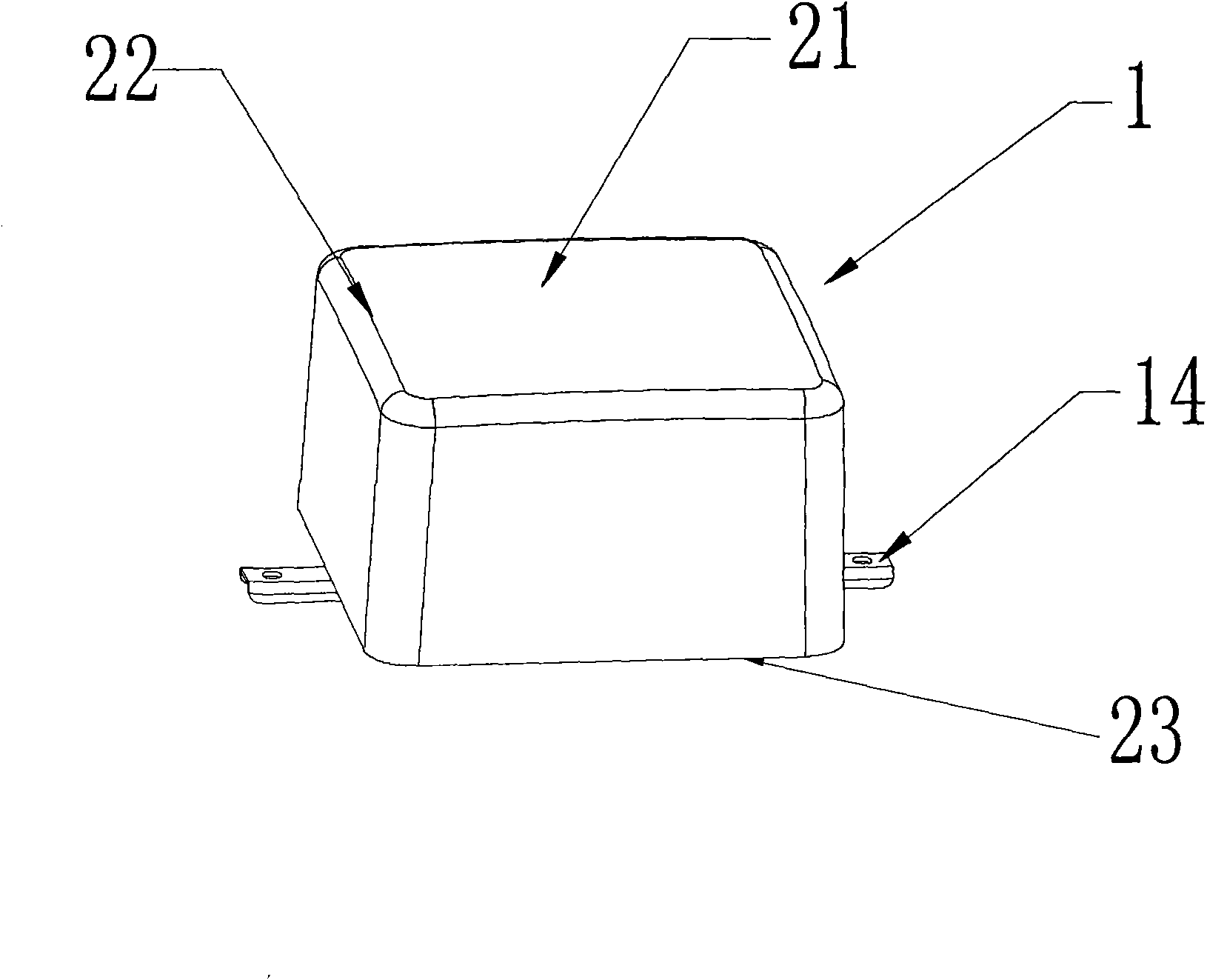
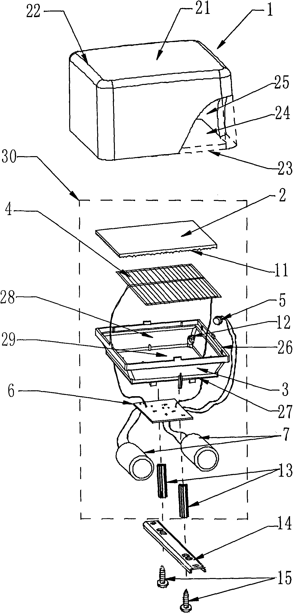
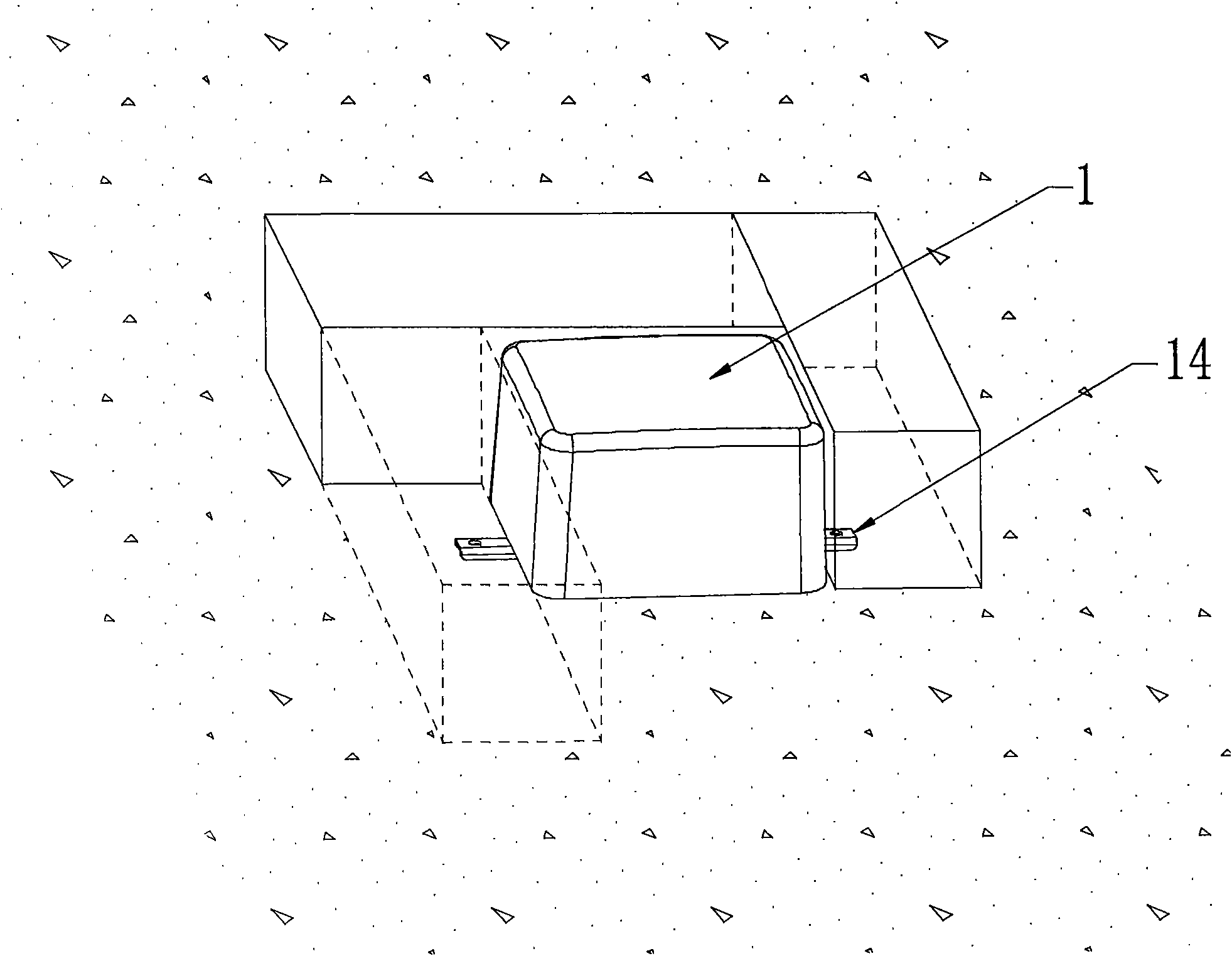
[0023] Such as figure 1 , 2As shown, in the preferred embodiment of the solar lighting device of the present invention, it includes a housing 1 and a solar cell module 30 . Wherein, the solar cell module 30 includes a concentrating plate 2 , an annular side reflector 3 , a solar cell string 4 , a luminous body 5 , a circuit board 6 and an energy storage device 7 . A cavity 25 is provided inside the casing 1 for accommodating the solar cell module 30, thereby preventing rainwater or other impurities in the environment from affecting the solar cell module 30; and a part of the casing 1 is provided with a light-transmitting area 21 for light penetrate. The light-transmitting region 21 can be arranged on the top 22 of the casing 1, and the solar cell module 30 is put into the casing cavity 25 from the opening 24 of the bottom 23 of the casing, and then the opening 24 is sealed with a filler or otherwise sealed. . The light emitted by the illuminant 5 at night can pass through ...


PUM


Abstract

The invention relates to a solar energy illumination device, comprising a shell provided with a transmission region at top and a solar energy cell module arranged inside the chamber of the internal of the shell. The solar energy cell module comprises a light-collecting board, a ring-shaped side reflecting disk, a solar energy cell serial group, a luminous body, an electronic control circuit and an energy storage device. The top of the ring-shaped side reflecting disk is covered and sealed with the light-collecting board and close to the transmission region of the shell. The solar energy illumination device also comprises the solar energy cell serial group which is arranged at the center of the inner side at the bottom of the ring-shaped side reflecting disk, the luminous body which is arranged inside the ring-shaped side reflecting disk and a circuit board which is arranged inside the chamber and controls the working of the luminous body and the solar energy cell serial group. The circuit board is provided with the energy storage device which can store the energy generated by the solar energy cell serial group in daylight and provide energy for the illumines body at night. By arranging the side reflecting disk, the energy-collecting efficiency of the solar energy cell serial group is improved and the working time of the luminous body at night is prolonged. The solar energy illumination device is waterproof, shockproof and maintenance-free.

Description

【Technical field】 [0001] The present invention relates to a lighting device, more specifically, to a solar lighting device used in outdoor ground or walls. 【Background technique】 [0002] In recent years, solar lighting devices have been used on outdoor ground or building surfaces, such as roads, sidewalks, stairs, outdoor walls, etc., to guide pedestrians or generate various lighting to decorate buildings. In this solar lighting device, the solar panel is used to charge the energy storage device during the day, and the stored electricity is used to supply power to the lighting device at night, thereby generating light at night. [0003] Existing solar lighting devices usually include a housing with a light-transmitting area and LEDs arranged in the housing, a solar panel that converts light energy into electrical energy, an energy storage device that stores electricity generated by the solar panel, such as a supercapacitor, and controls the solar battery. board and the cir...

Claims


Application Information

Patent Timeline
Patent Type & Authority Applications(China)
IPC IPC(8): F21S9/03F21V23/00F24J2/00H02J7/00F21W131/10F21Y101/02F21Y115/10
CPCY02E10/40Y02B20/72
Inventor 哈罗德·埃米尔·福诺
Owner SOL LITE MFG
Why Eureka
Try Eureka