Piezoelectric structure damping control electronic compensation method

A technology of damping control and piezoelectric structure, applied in the field of piezoelectric structure damping control, piezoelectric structure damping control electronic compensation method, which can solve the problems of system instability and satisfaction.

Inactive Publication Date: 2012-01-04
BEIHANG UNIV
View PDF1 Cites 0 Cited by
  • Summary
  • Abstract
  • Description
  • Claims
  • Application Information

AI Technical Summary

Problems solved by technology

However, the experimental results are not so satisfactory
with g s g a However, the system tends to be unstable, producing high-frequency or very low-frequency self-excited vibrations, and the increment of the modal damping ratio has not yet reached the desired requirement such as 0.1

Method used


Image

  • Piezoelectric structure damping control electronic compensation method
  • Piezoelectric structure damping control electronic compensation method
  • Piezoelectric structure damping control electronic compensation method

Examples


Embodiment Construction

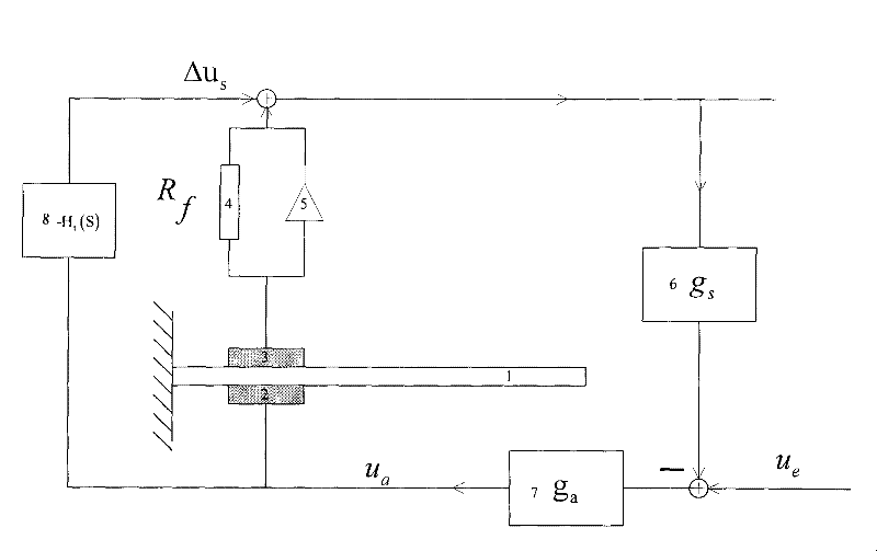
[0265] See figure 2 As shown, the present invention is an electronic compensation method for piezoelectric structure damping control, which is illustrated by taking a beam as an example. The specific steps of the method are as follows:

[0266] Step 1: Determine the compensation link. h t (s) is the propagation characteristic of the strain wave along the thickness direction of the beam, and its first-order natural frequency is very high, so within the frequency band to be controlled by the beam, it can be regarded as a proportional link, or more precisely, using a It is easy to implement an inertial link to approximate it

[0267] H t ( ω ) ≈ g t 1 + jω / Ω c - - - ...


PUM


Abstract

The invention discloses a piezoelectric structure damping control electronic compensation method, which comprises the following: step 1, determining a compensation link; step 2, obtaining omega<c>; and step 3, obtaining g<t>. The damping control method provided by the invention overcomes the defects in the prior art, eliminates the feedback of partial excitation strain of a piezoelectric actuating piece so as to make a mathematic model of a piezoelectric structure return to a theoretical model, has skillful design and simple operation, and can be widely applied in the technical field of structural vibration active control.

Description

(1) Technical field [0001] The invention relates to a piezoelectric structure damping control method, in particular to an electronic compensation method for piezoelectric structure damping control, which belongs to the technical field of structural vibration active control. (2) Background technology [0002] At present, the damping control of piezoelectric structures recorded in many literatures adopts a typical control mode - a closed-loop system composed of speed negative feedback. In the present invention, the piezoelectric beam is used as a typical structure to explain the principle of a typical control mode and the control method of the present invention, but the method is also applicable to various other structures. [0003] figure 1 It is a schematic diagram of a typical control mode adopted by many literatures. It can be seen from the figure: [0004] 1. A piezoelectric actuator 2 is attached to the lower surface of the beam 1, and a piezoelectric measuring sheet 3...

Claims


Application Information

Patent Timeline
Patent Type & Authority Patents(China)
IPC IPC(8): G05D19/00
Inventor 姚军李晓钢王晓红熊泽涛袁虹叶建华
Owner BEIHANG UNIV
Why Eureka
Try Eureka