
Device and method for selective soldering

A selective, solder technology, used in tin feeding devices, welding equipment, assembling printed circuits with electrical components, etc., can solve problems such as the increase in the error rate of metal scrap, reduce pollution and error rates, improve efficiency, and improve welding quality. improved effect

Inactive Publication Date: 2009-10-21
LINDE AG +1
View PDF2 Cites 4 Cited by
  • Summary
  • Abstract
  • Description
  • Claims
  • Application Information

AI Technical Summary

Problems solved by technology

Likewise, minor inerting during the welding process and the associated increase in metal scrap and increased error rates are defects to be mentioned

Method used


Image

  • Device and method for selective soldering
  • Device and method for selective soldering

Examples


Embodiment Construction

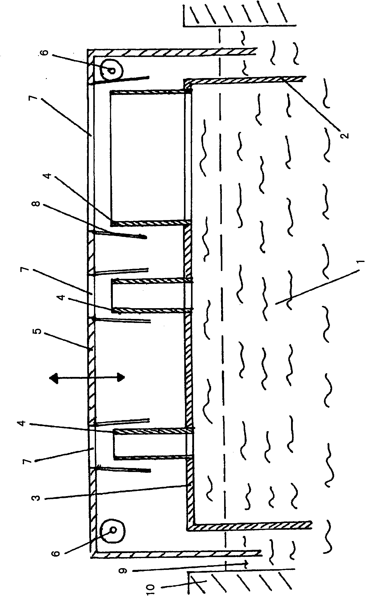
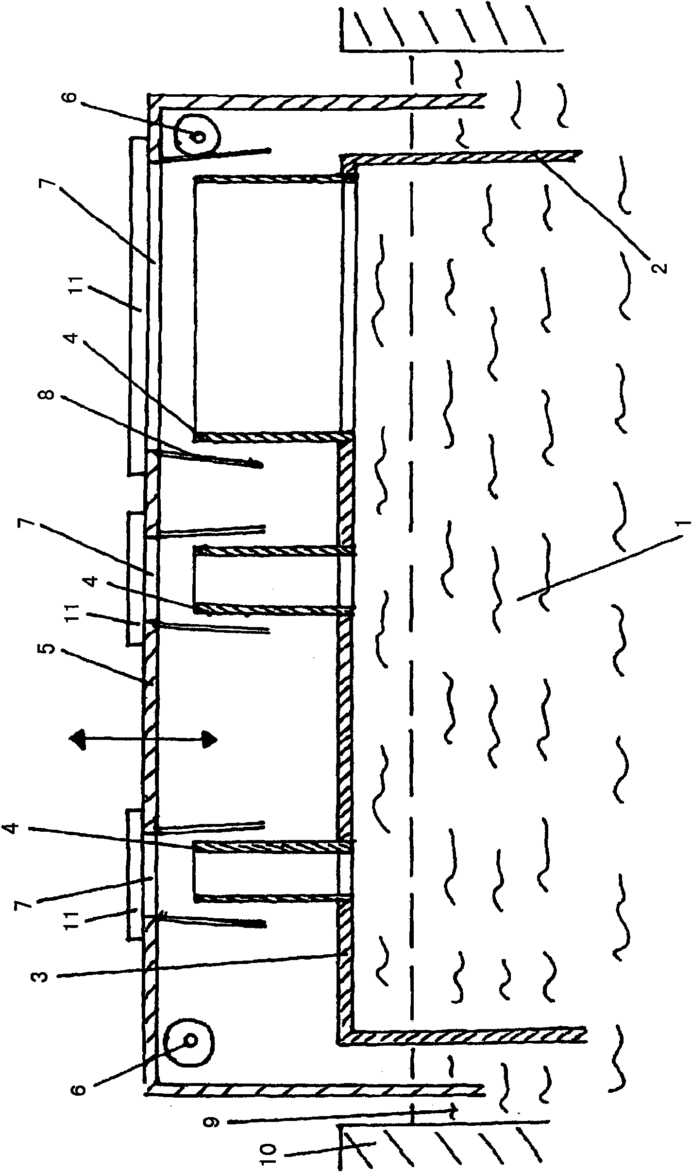
[0031] figure 1 A container 10 for liquid solder is shown, which contains a so-called solder bath 9 with solder channels 2 . The drawing further shows three nozzles 4 mounted on the solder channel 2 . In this example, the solder channel 2 is generally embodied as a pressure channel and is closed to the surrounding environment. Solder channel 2 on figure 2 Only part of it is drawn.

[0032] The nozzle 4 is mounted on the solder channel 2 in the region of the cover sheet 3 and is secured by said solder channel 2 . In order to pressurize the liquid solder 1, a structure of a solder pump (not shown) is provided. The solder channel 2 is surrounded by a vertically movable cover 5 which is immersed in the solder bath 9 or otherwise sealed to the surface of the solder bath 9 . A channel 7 for each nozzle 4 is provided in the cover 5 . Furthermore, in this example two protective gas delivery devices 6 are provided, which achieve the purpose of delivering the protective gas under...


PUM


Abstract

The invention relates to a first device for selective soldering, comprising a container (10) for liquid solder, with a so-called soldering bath (9), with a soldering channel (2) and at least one nozzle (4) mounted on the soldering channel (2), and with a soldering pump for pressurizing liquid solder (1) in the soldering channel (2), characterized in that the soldering channel (2) is surrounded by a vertically moveable hood (5), which immerses in the soldering bath (9), or which is sealed against the surface of the soldering bath (9) in another manner, and which comprises a passage (7) for each nozzle (4). The invention further comprises at least one feeding device (6) for protective and / or active gas underneath the hood (5), wherein flow plates (8) are attached to the hood (5), the plates extending substantially downward in the direction of the soldering bath from the hood. The invention further relates to a method for selective soldering.

Description

technical field [0001] The invention relates to a device for selective soldering comprising a liquid solder container containing a so-called solder bath with a solder channel and at least one nozzle mounted on the solder channel with a pair of A solder pump that pressurizes the liquid solder in the solder channel. The present invention further relates to a method for selective soldering. Background technique [0002] Selective soldering is a well-established method for soldering electronic components. It has proven to be particularly advantageous especially for large and bulky components, such as transformers, plugs, electrolytic capacitors and others, which are subject to high mechanical stress, for example, preferably said components according to the so-called push-through technique in the selective soldering method ( push-through technique) for welding. The selective soldering method can be considered as a spot soldering technique, for most parts the liquid solder is a...

Claims


Application Information

Patent Timeline
IPC IPC(8): B23K1/08B23K3/06H05K3/34B23K101/42
CPCB23K3/0684H05K3/3468H05K3/3447B23K2201/42B23K1/085H05K2203/0763B23K2101/42
Inventor H·艾斯勒E·万德克
Owner LINDE AG
Learn More