Electro-optical yarn sensor

A sensor and yarn technology used in optical device exploration, textile and papermaking, looms, etc. to improve reading quality and compensate for manufacturing and assembly tolerances

Inactive Publication Date: 2011-08-31
IRO AB
View PDF3 Cites 0 Cited by
  • Summary
  • Abstract
  • Description
  • Claims
  • Application Information

AI Technical Summary

Problems solved by technology

Unavoidable manufacturing and assembly tolerances spoil the reading quality of the receivers and cause severe scanning fluctuations in a series of yarn feeding devices equipped with theoretically identical yarn sensors

Method used


Image

  • Electro-optical yarn sensor
  • Electro-optical yarn sensor
  • Electro-optical yarn sensor

Examples


Embodiment Construction

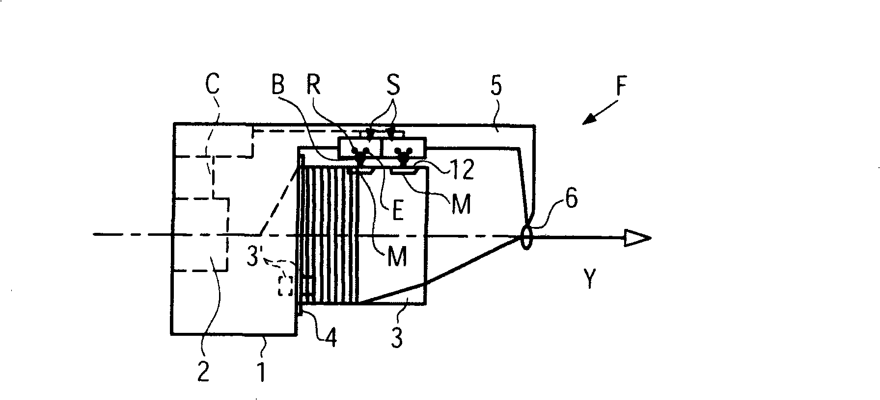
[0032] figure 1 The yarn feeding device F in a loom, such as a weft yarn feeding device of a loom or a knitting yarn feeding device of a knitting machine, includes a housing 1 that includes an electric motor 2 and a drum-shaped yarn storage body 3 . The storage body 3 is rotatably supported on a not shown drive shaft, however, is hindered to rotate with the drive shaft (fixed storage drum) by a co-operating magnet 3'. In an alternative not shown, the yarn feeding device can alternatively be equipped with a rotatable yarn storage body. The drive shaft drives a winding element 4 which winds the yarn Y inserted into the yarn feeding device F from the left onto adjacent windings on the periphery of the yarn storage body 3 . The yarn is then unwound from the foremost winding on the storage body 3 and optionally passed axially through the exit hole 6 . The housing has a housing support 5, in the embodiment shown, in which two photoelectric yarn sensors S are fixedly mounted, said...


PUM


Abstract

A yarn feeding device F comprises at least one electro-optical yarn sensor S having at least one combination of a light source E and a physically closely adjacent receiver R. In the light path betweenthe light source / receiver combination and a reflective scanning zone 12 on a storage body of the yarn feeding device a transparent optical spreading body B is provided which spreads a substantially round light spot 17 into a longitudinal light strip in the reflective yarn scanning zone 12, the transparent spreading body B being arranged such that the longitudinal axis of the light strip is oriented substantially parallel to the axes of the windings of a yarn Y carried by the storage body periphery.

Description

technical field [0001] The invention relates to a yarn feeding device according to the preamble of claim 1 and to an optoelectronic yarn sensor according to the preamble of claim 16 . Background technique [0002] DE-A-19612953 discloses an optoelectronic yarn sensor in a yarn feeding device comprising a fence-like reflective strip delimited by strip-shaped holes or laterally arranged hole regions. Only part of the light from the light source is used to scan the yarn. [0003] The photoelectric yarn sensor of the yarn feeding device of WO 00 / 48934 A has as light source an LED or a laser diode, a laser diode, a so-called VCSEL (Vertical Cavity Surface Emitting Laser), which can generate a reflected yarn directly towards the storage body. Narrow cone beam in the line scan area. This beam produces a very circular spot on the scanning area, ie an annular and small spot. The scanning zone is retroreflective, ie reflects light in the same direction as it hits the scanning zone...

Claims


Application Information

Patent Timeline
Patent Type & Authority Patents(China)
IPC IPC(8): G01V8/14
CPCD03D47/367
Inventor 耶克尔·赫尔斯特伦
Owner IRO AB
Why Eureka
Try Eureka