Exhaust duct

A technology for exhaust pipes and pipe bodies, which is applied in vertical pipes, building components, buildings, etc., and can solve problems such as series pressure, affecting exhaust effect, and difficulty in setting bottom molds

Inactive Publication Date: 2009-10-28
张琦
View PDF0 Cites 8 Cited by
  • Summary
  • Abstract
  • Description
  • Claims
  • Application Information

AI Technical Summary

Problems solved by technology

However, none of these manufacturers found another problem, that is, because there is no supporting device outside the pipe body, during the installation process, it is difficult to install the bottom form between the inner corner floor and the pipe gap, so the inner corner building was abandoned. The gap between the plate and the pipe is blocked, causing gas, odor, and pressure to occur between the exhaust layers of the system, thereby affecting the exhaust effect, and due to the existence of the gap, there are hidden dangers in the installation quality of the pipe

Method used


Image

  • Exhaust duct
  • Exhaust duct
  • Exhaust duct

Examples


Embodiment Construction

[0036] In order to make the object, technical solution and advantages of the present invention clearer, the present invention will be further described in detail below in conjunction with the accompanying drawings and embodiments. It should be understood that the specific embodiments described here are only used to explain the present invention, not to limit the present invention.

[0037] The purpose of the present invention is to propose an exhaust duct that can achieve the effect of sealing the gap between the exhaust duct and the floor after engineering installation, and can effectively prevent the occurrence of gas and odor due to poor sealing.

[0038] The present invention will be described in detail below in conjunction with specific embodiments and accompanying drawings.

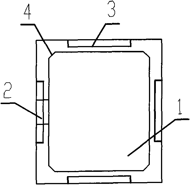
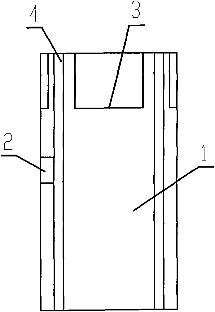
[0039] figure 1 and figure 2 As shown, the figure numbers shown in the figure are respectively the exhaust pipe body 1, the air inlet 2, the support platform 3, and the inner chamfer 4 in the fir...


PUM


Abstract

An exhaust duct comprises a hollow exhaust duct body, an air intake on the exhaust duct body, one or more than one backoff or projected brace table outside the exhaust duct body; the shaped of the brace tables are same or different; the bearing surface is horizontal or inclined or flattened or rough or normal or abnormal. The brace table is added on the prior exhaust duct body whatever the brace table is backoff or projected, in order to support, fix the bottom formwork between the duct and the floor plate aperture, therefore the aperture slurry sealing problem between the floor plate and the duct is solved, furthermore the gas staining, odor staining, pressure leakage between the layer and layer can be prevented and the invention also provides many preferable executive plans, such as adding various function components, duct material selection and design the material structure.

Description

technical field [0001] The invention relates to building pipes in the technical field of building materials, in particular to an exhaust pipe suitable for kitchens and toilets in various buildings. Background technique [0002] Exhaust pipes used in kitchens and bathrooms in previous buildings were designed to prevent the occurrence of smoke, gas, and odor between layers through internal structural design. In view of this, many manufacturers and even users have spent a lot of thought on solving this problem. However, none of these manufacturers found another problem, that is, because there is no supporting device outside the pipe body, during the installation process, it is difficult to install the bottom form between the inner corner floor and the pipe gap, so the inner corner building was abandoned. The gap between the plate and the pipe is blocked, causing gas, odor, and pressure to occur between the exhaust layers of the system, thereby affecting the exhaust effect, and...

Claims


Application Information

Patent Timeline
Patent Type & Authority Applications(China)
IPC IPC(8): E04F17/02
Inventor 张琦
Owner 张琦
Why Eureka
Try Eureka