Cover structure of electric pressure cooker

An electric pressure cooker and lid technology, which is applied to pressure cookers and other directions, can solve the problems of complex structure, complex process, hidden sanitation, etc., and achieve the effects of beautiful appearance, low cost and convenient operation.

Inactive Publication Date: 2009-11-04
FOSHAN FUSHIBAO ELECTRICAL APPLIANCE TECH
View PDF1 Cites 2 Cited by
  • Summary
  • Abstract
  • Description
  • Claims
  • Application Information

AI Technical Summary

Problems solved by technology

But this patented technology adopts many parts such as support piece, support seat, its structure is complicated, and cost is high, and process is complicated, and support piece or the cover teeth outside of inner pot lid and support seat are easy to accumulate scale, cause hygienic hidden danger

Method used


Image

  • Cover structure of electric pressure cooker
  • Cover structure of electric pressure cooker
  • Cover structure of electric pressure cooker

Examples


Embodiment 1

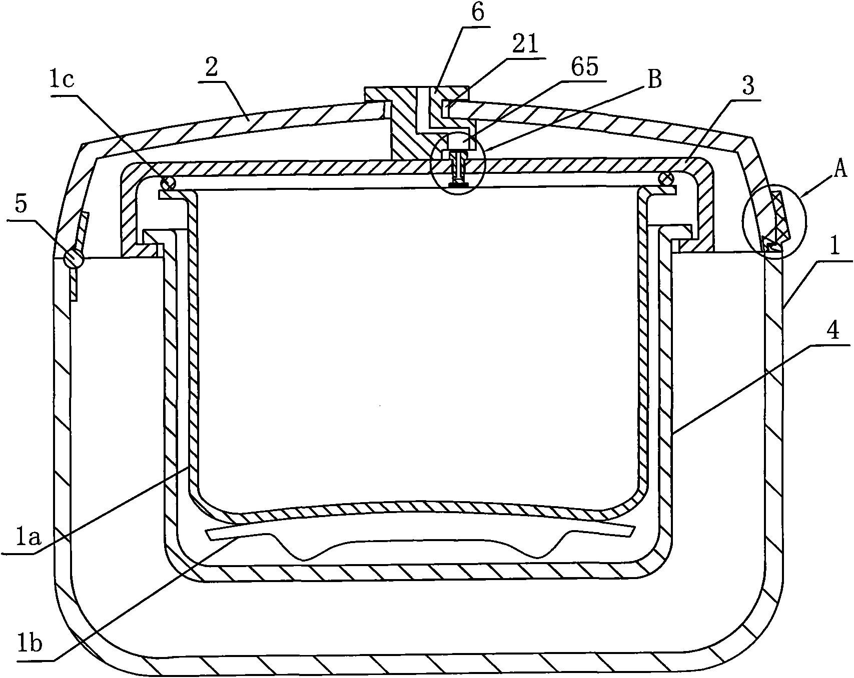
[0047] Such as figure 1 As shown, the general electric pressure cooker is divided into two parts: a pot cover and a pot body. The pot body generally includes a pot body shell, and an outer pot 4, an inner pot 1a, a heating plate 1b, etc. are installed in the pot body shell. The inside of the inner cover 3 is provided with a sealing ring 1c. After the lid is fastened, the sealing ring 1c presses against the edge of the inner pot 1a, thereby forming a sealed space between the inner pot 1a and the inner cover 3 . Hinge 5 is a mechanical connection device used to connect two objects and allow rotation between them. The flip connection between the surface cover 2 and the pot body 1 through the hinge 5 can realize that after the pot cover is opened, the pot cover is still connected and vertically supported on the pot body 1 .

[0048] The pot cover structure of the electric pressure cooker includes a face cover 2 and an inner cover 3 positioned below the face cover 2, the lower edg...

Embodiment 2

[0054] On the basis of Example 1, as Figure 6 As shown, a central rotating handle 8 can also be arranged on the surface cover 2, and the central rotating handle 8 is fixedly connected with the rotating central shaft 6. Certainly, the central rotating handle 8 and the rotating central shaft 6 may also be manufactured integrally by means of injection molding or the like. In this way, turning the central rotating handle 8 can unscrew or fasten the inner cover through the rotating central axis.

Embodiment 3

[0056] On the basis of Example 1, as Figure 7 and Figure 8 As shown, the rotating central shaft 6 includes an upper rotating shaft 62 and a lower rotating shaft 63, and the upper rotating shaft 62 and the lower rotating shaft 63 are fixedly connected with each other up and down. On the inner and outer sides of the surface cover 2 , the inner cover 3 is fixedly connected to the lower rotating shaft 63 of the rotating central shaft through the central hole 31 of the inner cover and the central hole 61 of the rotating shaft with a bolt 7 . The central rotating handle 8 can also be fixedly connected with the rotating central axis 6, so as to facilitate the user to open the inner cover.


PUM


Abstract

The invention discloses a cover structure of an electric pressure cooker, which comprises a surface cover and an inner cover below the surface cover; the inner cover is provided with fastening teeth which are mutually rotationally matched with an outer cooker body of the electric pressure cooker; and the surface cover and a cooker body are connected in an overturning way by a hinge. The cover structure is characterized in that: the central position of the surface cover is provided with a central hole of the surface cover and a rotating central shaft; the rotating central shaft is axially positioned and can be radially rotationally arranged in the central hole of the surface cover; and the inner cover is fixedly connected with the rotating central shaft. In the cover structure, the rotating central shaft is rotated to drive the inner cover fixedly connected with the rotating central shaft to rotate, so that the aim of opening or fastening a cover is achieved, and the cover structure is simpler and has lower cost. The technical proposal can be suitable for cover structures of various pressure cookers.

Description

technical field [0001] The invention relates to a pot cover of an electric pressure cooker, in particular to a cover structure of a flip-top electric pressure cooker. Background technique [0002] At present, the pot lid and pot body of electric pressure cookers on the market are mostly split, that is, the two are independent of each other. When the pot lid is opened, the pot lid must be removed and put aside separately, which takes up space and is inconvenient. For this shortcoming, someone has proposed the lid of the flip-top electric pressure cooker, as the patent application number is 200620063893.5, and the name is called " a kind of electric pressure cooker " Chinese utility model patent, discloses a kind of pot lid of electric pressure cooker through hinge shaft and The pot body is connected by rotation, and the pot cover includes a rotating handle, a surface cover and an inner pot cover. A supporting base is installed on the lower part of the surface cover, the inne...

Claims


Application Information

Patent Timeline
Patent Type & Authority Applications(China)
IPC IPC(8): A47J27/08A47J27/09
Inventor 陆社本
Owner FOSHAN FUSHIBAO ELECTRICAL APPLIANCE TECH
Why Eureka
Try Eureka