Non-contact ultrasonic tonometer

A non-contact, tonometer technology, applied in eye examinations, eye testing equipment, etc., can solve problems such as changes in measurement results

Inactive Publication Date: 2009-11-04
NIDEK CO LTD
View PDF5 Cites 7 Cited by
  • Summary
  • Abstract
  • Description
  • Claims
  • Application Information

AI Technical Summary

Problems solved by technology

In the case of measuring human eyes that exhibit involuntary eye movements and gaze shifts, the characteristics (e.g., frequency and phase) of the u

Method used


Image

  • Non-contact ultrasonic tonometer
  • Non-contact ultrasonic tonometer
  • Non-contact ultrasonic tonometer

Examples


Embodiment Construction

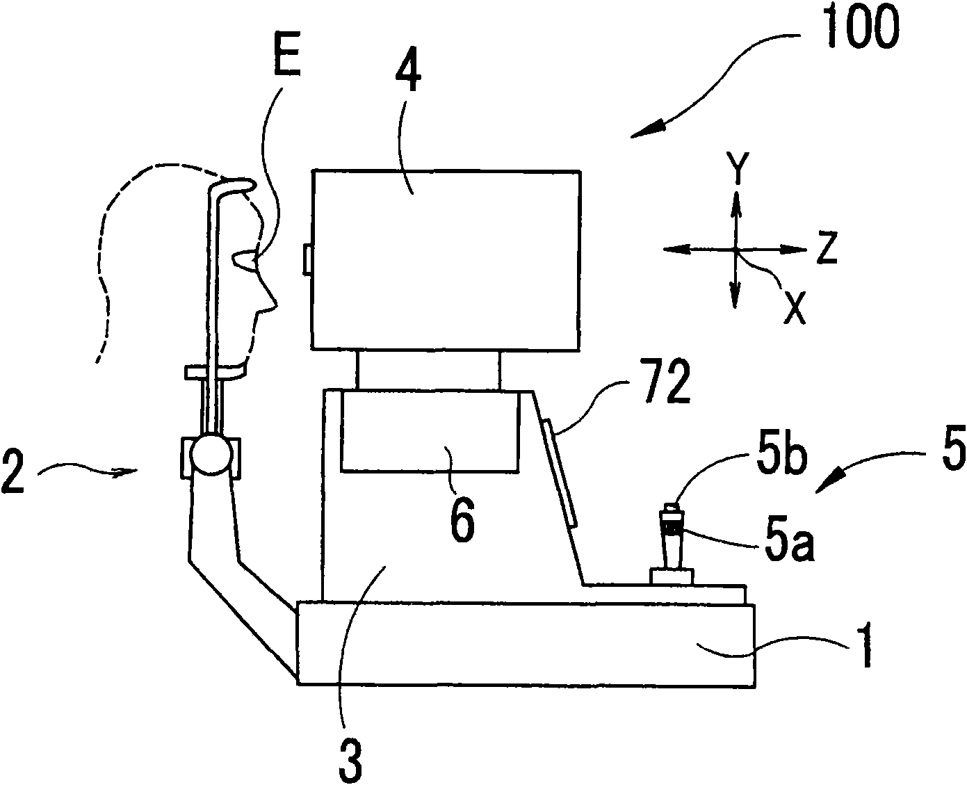
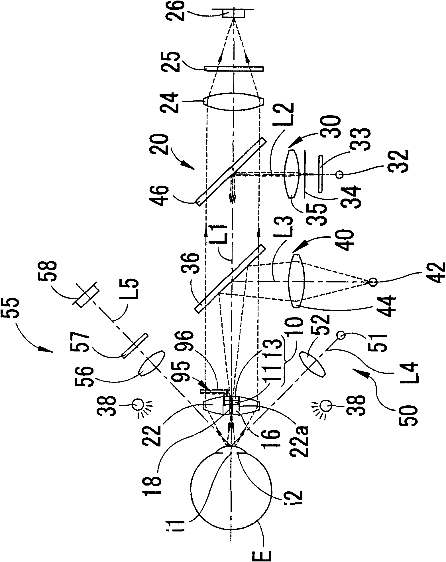
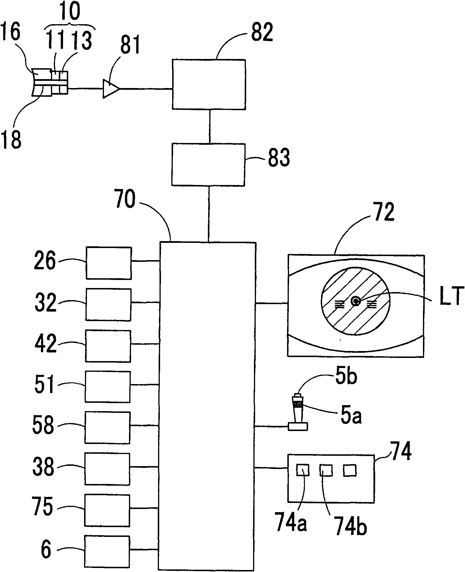
[0008] Preferred embodiments of the present invention will be described below with reference to the accompanying drawings. figure 1 It is a three-dimensional external view of the non-contact ultrasonic tonometer 100 of this embodiment.

[0009] The tonometer 100 is a so-called stationary device that includes a base 1, a head support unit 2 attached to the base 1, a movable unit 3 movably equipped on the base 1, and a movable unit 3 movably equipped on the base 1. The measurement part 4 on the tonometer 100 includes a measurement system and an optical system mentioned later. The measuring part 4 is provided in the right and left direction (X direction), up and down direction (Y direction), and back and front direction (working direction) with respect to the subject's eyes E by the moving part 6 equipped in the movable unit 3. Distance direction; Z direction) movement. The movable unit 3 is moved in the X and Z directions on the base 1 by tilting the joystick 5 . The measurin...


PUM


Abstract

A non-contact ultrasonic tonometer for measuring intraocular pressure of an examinee's eye in non-contact manner by use of an ultrasonic wave comprises: a probe including a vibrator for making the ultrasonic wave incident on the examinee's eye and a sensor for detecting the ultrasonic wave reflected from the examinee's eye; and an observation optical system for observing an anterior segment of theeye, wherein the probe is placed in an optical path of the observation optical system, and the observation optical system forms an image of the anterior segment through a surrounding region of the pr obe.

Description

technical field [0001] A non-contact ultrasonic tonometer for measuring the intraocular pressure of an eye of a subject by ultrasound in a non-contact manner. Background technique [0002] A contact intraocular pressure examination apparatus has been proposed for measuring intraocular pressure by pressing the eye with the tip of a probe holding a probe device including a vibrator for introducing vibration into the eye and a A probe device for a vibration detection sensor that detects vibrations reflected by eyes (see Patent Document 1: JP2004-267299A). [0003] There has also been proposed a non-contact intraocular pressure measurement system for measuring intraocular pressure by entering ultrasonic waves into the eye (actually, a model of the eyeball) and by detecting the reflected ultrasonic waves from the eye with a sensor (see Non-Patent Document 1 : "Development of a New Non-Contact Intraocular Pressure Measurement System Using the Phase-Shift Method", Masayuki JINDE a...

Claims


Application Information

Patent Timeline
IPC IPC(8): A61B8/10
Inventor 三轮哲之
Owner NIDEK CO LTD
Why Eureka
Try Eureka