Electric motors and generators with opposing non-contact piezoelectric bearing supports

a technology of piezoelectric bearings and electric motors, which is applied in the direction of sliding contact bearings, mechanical energy handling, mechanical apparatus, etc., can solve the problems of significant technological difficulty in their implementation, relatively poor technical specifications and performance of motors of this type, and relatively low load-bearing capacity, so as to improve specific weight carrying ability, improve technical characteristics, and reduce the moment of friction force and power consumption

Inactive Publication Date: 2012-03-01
DTI MOTION CORP
View PDF0 Cites 7 Cited by
  • Summary
  • Abstract
  • Description
  • Claims
  • Application Information

AI Technical Summary

Benefits of technology

[0011]The inventive concepts relate to economical motors and generators each with a fixed axis that uses ultrasound contactless support. Electric motors and generators with improved technical c

Problems solved by technology

A shortcoming of motors incorporating various electrostatic, magnetic, and superconducting contactless suspensions/supports is the significant technological difficulty involved in their implementation.
This has contributed to relatively poor technical specifications and performance for motors of this type.
For example, such motors tend to have relatively low load-bearing capacity, produce adverse torques, and involve complicated stabilization in space on account of considerable gaps and so on.
The technological difficulties associated with such motors has also resulted in devices which have relatively high cost.
Accordingly, motors incorporating these principles have failed to find broad application in commercial practice.
However, these references are generally limited to various generic supports as opposed to motors arrangements.
Among the disadvantages of the gas support

Method used


Image

  • Electric motors and generators with opposing non-contact piezoelectric bearing supports
  • Electric motors and generators with opposing non-contact piezoelectric bearing supports
  • Electric motors and generators with opposing non-contact piezoelectric bearing supports

Examples


first embodiment

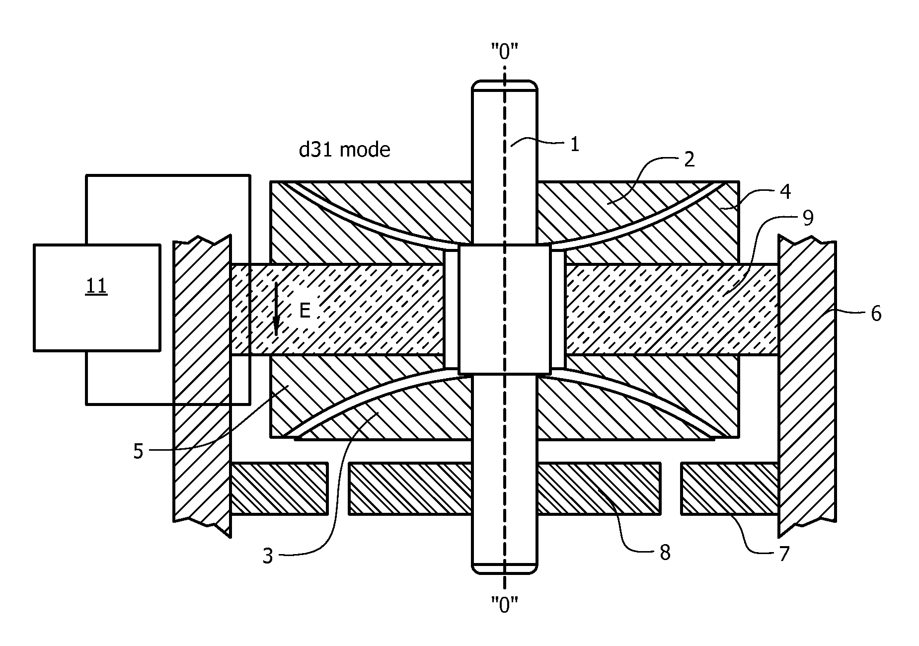
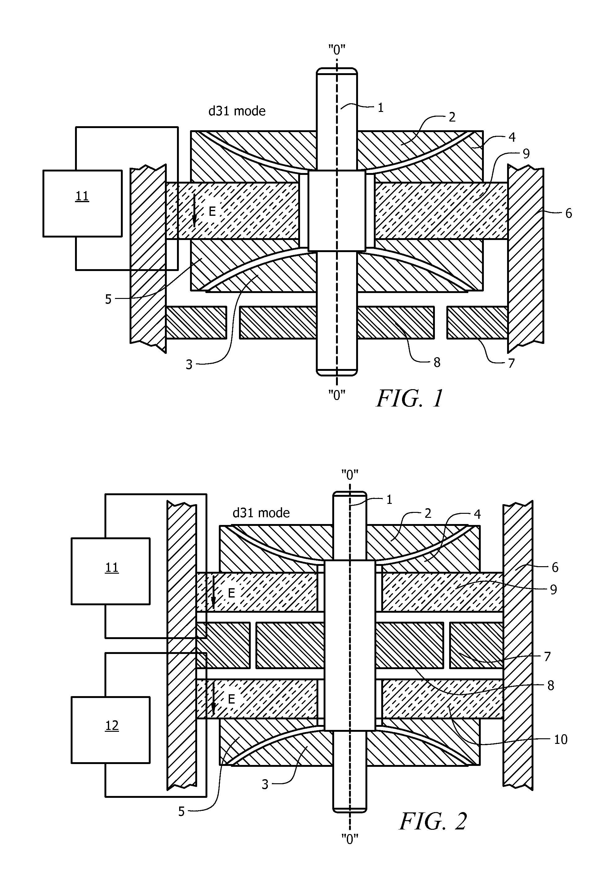
[0062]Referring now to FIG. 1, there is shown the electric motor. The electric motor includes a rotor and a stator. The rotor includes an axle 1, upper and lower spherical trunnions 2, 3, and a rotor winding 8. The stator includes annular shaped upper and lower saddles or saddle-resonators 4, 5, a stator winding 7, and a piezoelectric element or piezoelement 9. The piezoelement 9 is excited by an excitation generator 11. The axle 1, upper and lower spherical trunnions 2, 3, upper and lower saddle-resonators 4, 5, stator 7, rotor 8, and piezoelement 9 can be contained within a motor housing 6 as shown.

[0063]The axle 1 is positioned symmetrically along a symmetry axis O-O (which is also referred to herein as a motor axis) on which the spherical upper trunnion 2 and lower trunnion 3 are centered and fastened. In this context, centering implies alignment of the center of the sphere (as defined by the curvature of the trunnion) with the axis of symmetry. The upper and lower spherical tru...

second embodiment

[0071]Referring now to FIG. 2, there is shown the electric motor. The electric motor in FIG. 2 comprises an axle 1 on which are centered and fixed the upper 2 and lower 3 spherical trunnions. The trunnions 2, 3 contact along a similar spherical surface (shaped as a spherical ring) with the respective upper 4 and lower 5 annular saddle-resonators situated intermediate the trunnions 2 and 3. Piezoelements 9, 10 are polarized normally to the planar end surfaces, and electrodes of the piezoelements 9, 10 are formed on these surfaces. The piezoelements 9, 10 are secured on the housing 6 which also supports the stator winding 7, while the rotor winding 8 is mounted on the axle 1. The axial play in the system amounts from several to tens of microns. In this embodiment of the motor a second generator 12 is added for excitation of the second piezoelement 10.

[0072]The electric motor illustrated in FIG. 2 operates as follows. Sine wave excitation voltages are supplied by the two independent ge...

third embodiment

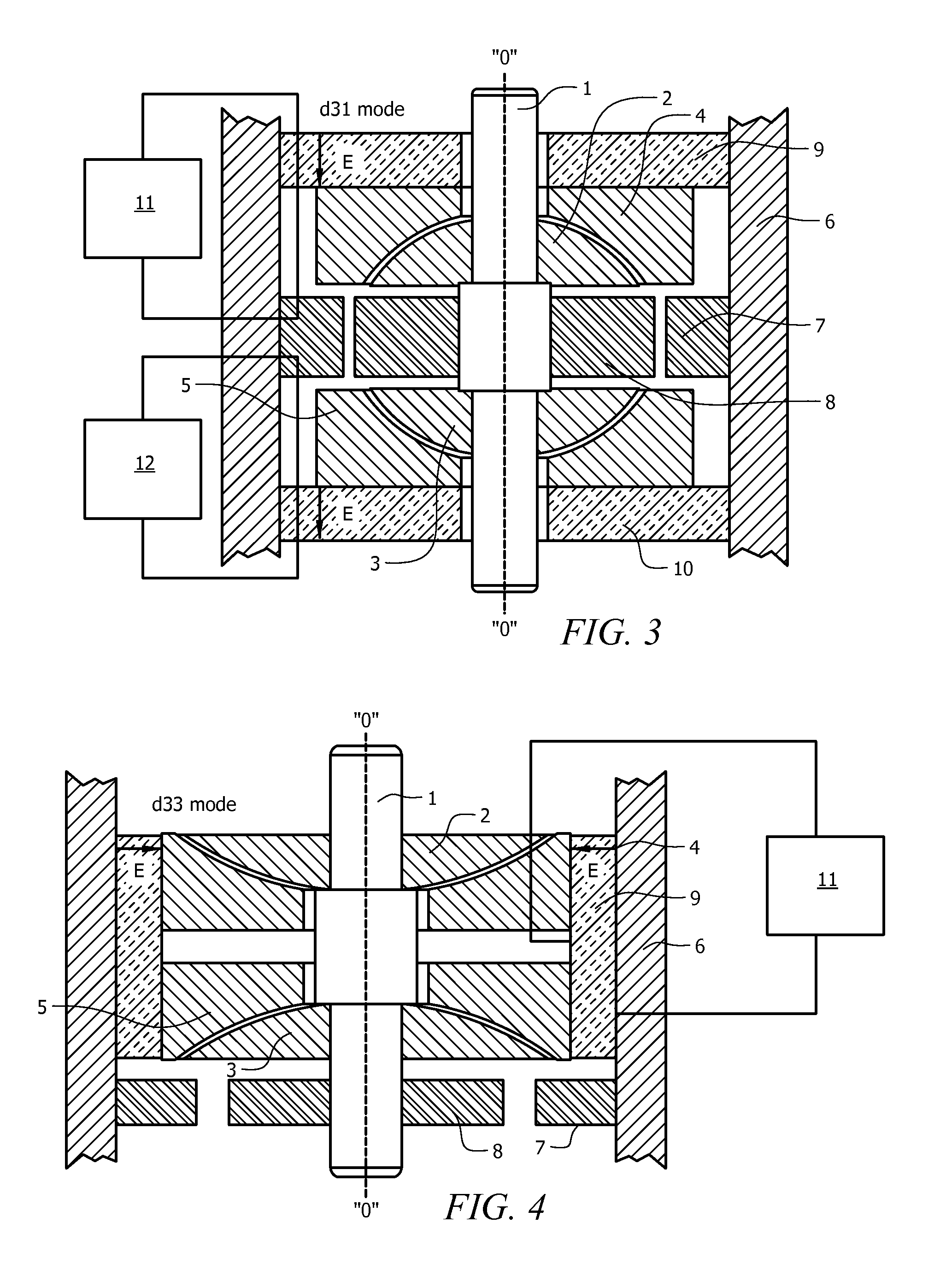
[0074]the electric motor with internally-situated trunnions 2, 3 is disclosed in FIG. 3. The internally-situated trunnions 2, 3 advantageously provide enhanced rigidity. This arrangement also allows expanding the functionality of the electric motor. For instance, when the spherical centers of the upper and lower trunnions 2, 3 coincide, a design of the electric motor with a floating shaft is implemented. More particularly, in the design shown in FIG. 3 (and in FIG. 6) the trunnion can slide (rock) on the cradle (when their spherical centers coincide) simultaneously. With the remaining designs described herein the rocking of the axis is restricted insofar as they allow only rotational movement.

[0075]The third embodiment of the electric motor, FIG. 3, comprises an axle 1 on which are centered and fixed the upper 2 and lower 3 spherical trunnions. The trunnions 2, 3 are in close proximity to the respective upper 4 and lower 5 annular saddle-resonators, along a spherical surface (shaped...


PUM


Abstract

Electric motors and generators, in which a non-contact ultrasonic suspension of the rotor of the electric motor, are provided. The non-contact ultrasonic suspension is achieved by the formation of an elevated-pressure gaseous microfilm between conjugated surfaces of saddle-resonators and trunnions of a bearing system.

Description

CROSS-REFERENCE TO RELATED APPLICATIONS[0001]This application claims the benefit under 35 U.S.C. §119(e) of U.S. Provisional Application No. 61 / 378,703, filed Aug. 31, 2010, the contents of which are incorporated by reference herein in their entirety.BACKGROUND OF THE INVENTION[0002]1. Statement of Technical Field[0003]The invention relates to the field of electric motors, generators, and other devices having rotating components suspended from non-contact bearings.[0004]2. Description Of Related Art[0005]Brushless motors operating on direct or alternating current are well known in the art. Such motors typically comprise a brushless acceleration unit, which includes a stator and a rotor, and an axial system. In the conventional synchronous or asynchronous brushless motors, the stator windings generate a rotating electromagnetic field. The rotating electromagnetic field interacts with the electromagnetic field of the rotor windings or with the permanent magnet field of the rotor, whic...

Claims


Application Information

Patent Timeline
IPC IPC(8): H02K7/08F16C32/06
CPCF16C17/10H02K7/08F16C32/0603
Inventor PETRENKO, SERHIYZHELYASKOV, VALENTIN R.
Owner DTI MOTION CORP
Why Eureka
Try Eureka