
Multifunctional power electric transformer

A technology of power electronics and transformers, applied in the direction of converting AC power input to DC power output, electrical components, output power conversion devices, etc., can solve the impact of sensitive loads, insulating oil pollutes the environment, and cannot achieve transformer fault current and voltage isolation. and other problems, to achieve the effect of solving the voltage sag/swell, increasing the transient stability limit, and improving the electrical environment of the power grid

Inactive Publication Date: 2009-11-04
SOUTHEAST UNIV
View PDF0 Cites 51 Cited by
  • Summary
  • Abstract
  • Description
  • Claims
  • Application Information

AI Technical Summary

Problems solved by technology

Although the traditional power transformer has the advantages of simple manufacturing process and high reliability, it can only realize voltage level conversion and insulation isolation, and its function is relatively single. Moreover, due to the electromagnetic coupling between the primary and secondary sides of the transformer, it is impossible to realize fault current and voltage on both sides of the transformer. The isolation of faults limits the scope of faults; the isolation of distorted currents and interference voltages on both sides of the transformer cannot be achieved. On the one hand, sensitive loads are affected, and on the other hand, the power grid is polluted; Circulation, insulating oil pollution and other issues

Method used


Image

  • Multifunctional power electric transformer
  • Multifunctional power electric transformer

Examples


Embodiment Construction

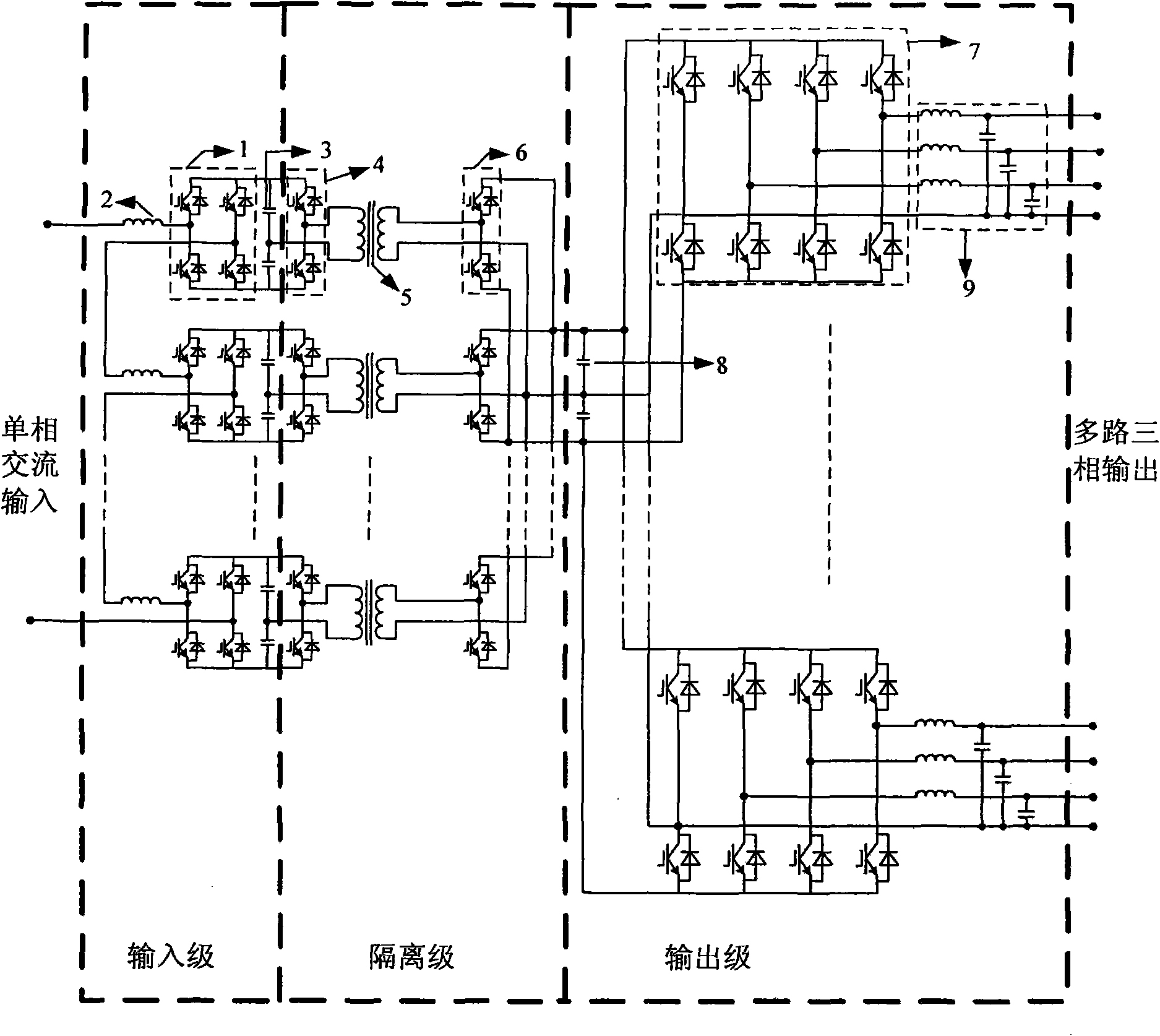
[0024] This multi-functional power electronic transformer adopts the technical solution of cascade connection on the high voltage side and parallel connection on the low voltage side. The three-phase structures are independent and identical, and the circuit topology of a certain phase is as follows: figure 1 As shown, the overall structure is divided into three stages: input stage, isolation stage, and output stage. The input stage is formed by cascading multiple sets of power converters, and the number of cascades is determined by the voltage level and the level of the selected power electronic devices (for example, when the high-voltage side voltage is 10kV and the switching device is 1200V / 600A, 13 converter stages are required couplet). Each cascaded power converter is a single-phase fully-controlled bridge composed of four fully-controlled devices, and a reactor is connected in series with the AC side of each single-phase fully-controlled bridge to achieve harmonic suppre...


PUM


Abstract

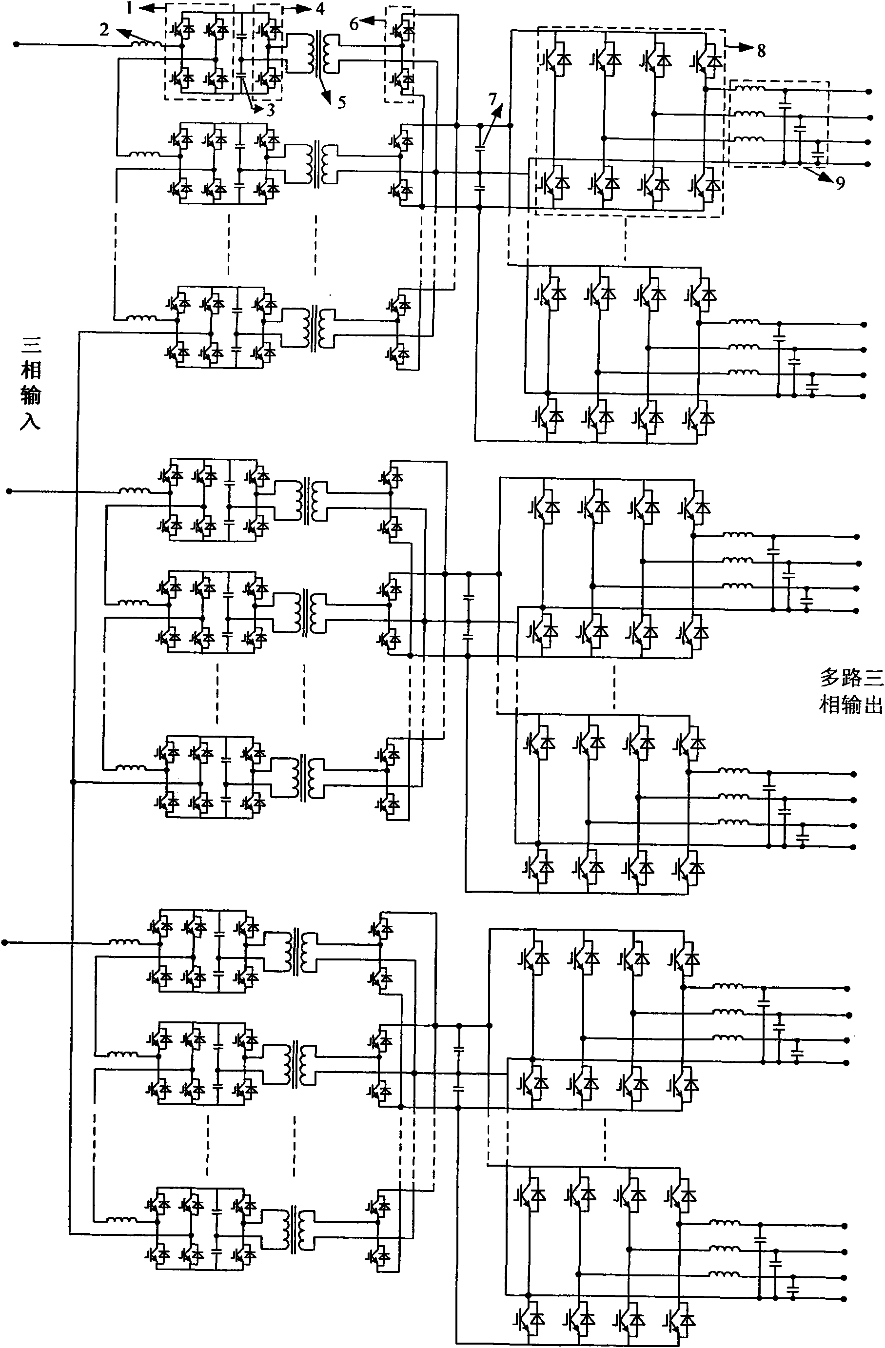
The invention provides a multifunctional power electric transformer. The multifunctional power electric transformer is divided into three levels, namely an input level, an isolation level and an output level, wherein the input level adopts an H bridge cascaded topological structure to meet the requirements on different input voltage levels; the isolation level adopts a mode of parallel connection of a plurality of high-frequency transformers, the DC / AC high-frequency modulation and the AC / DC high-frequency modulation in an isolation link both adopt a single-phase fully controlled half-bridge structure to save switch parts; the output level consists of one or more three-phase voltage source convertors which are connected in parallel, so that the multi-output can be realized according to the need of a load; and the convertors of the output level are also connected with an LC wave filter to improve the waveform quality of the voltage and the current. The whole device fully adopts technically mature power parts, and each layer cascaded with the input level and the corresponding isolation level can be combined into a convertor, thereby facilitating the design and the production of the convertors. Besides simple functions of voltage conversion and isolation and energy transfer, which can be realized by the conventional transformer, the multifunctional power electric transformer can also realize other novel functions meeting the needs of a power system.

Description

technical field [0001] The invention relates to a power transmission and distribution device capable of realizing multiple functions, and belongs to the technical field of power electronics applied in power systems. Background technique [0002] Since its invention in the 19th century, power transformers have become the basic components of power transmission and distribution systems. Although the traditional power transformer has the advantages of simple manufacturing process and high reliability, it can only realize voltage level transformation and insulation isolation, and its function is relatively single. Moreover, due to the electromagnetic coupling between the primary and secondary sides of the transformer, it is impossible to realize fault current and voltage on both sides of the transformer. The isolation of faults limits the scope of faults; the isolation of distorted currents and interference voltages on both sides of the transformer cannot be achieved, which on th...

Claims


Application Information

Patent Timeline
IPC IPC(8): H02M5/44H02M7/483
Inventor 赵剑锋倪喜军黄华闫安心
Owner SOUTHEAST UNIV
Learn More