
Medical system

A technology for medical and guiding components, which is applied in the field of medical systems, and can solve problems such as difficult to reliably move the grip part and unreliable transmission of driving force

Active Publication Date: 2009-11-11
OLYMPUS CORP
View PDF0 Cites 8 Cited by
  • Summary
  • Abstract
  • Description
  • Claims
  • Application Information

AI Technical Summary

Problems solved by technology

[0003] In the medical system disclosed in U.S. Patent Application Publication No. 2005 / 70757, when the base end of the flexible tube is driven by the driving device instead of manually, the flexible tube is connected between the driving device and the forceps. The openings are in a floating state, and the driving force applied to the proximal end of the flexible tube cannot be reliably transmitted to the gripping portion of the distal end, making it difficult to reliably move the gripping portion

Method used


Image

  • Medical system
  • Medical system
  • Medical system

Examples


Embodiment Construction

[0042] Hereinafter, various embodiments of the present invention will be described with reference to the drawings.

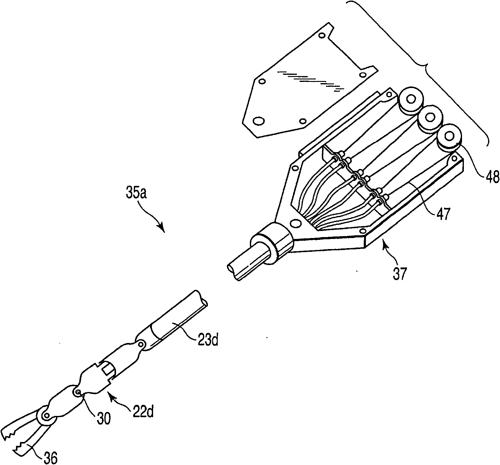
[0043] Figure 1 to Figure 7 The first embodiment of the present invention is shown.

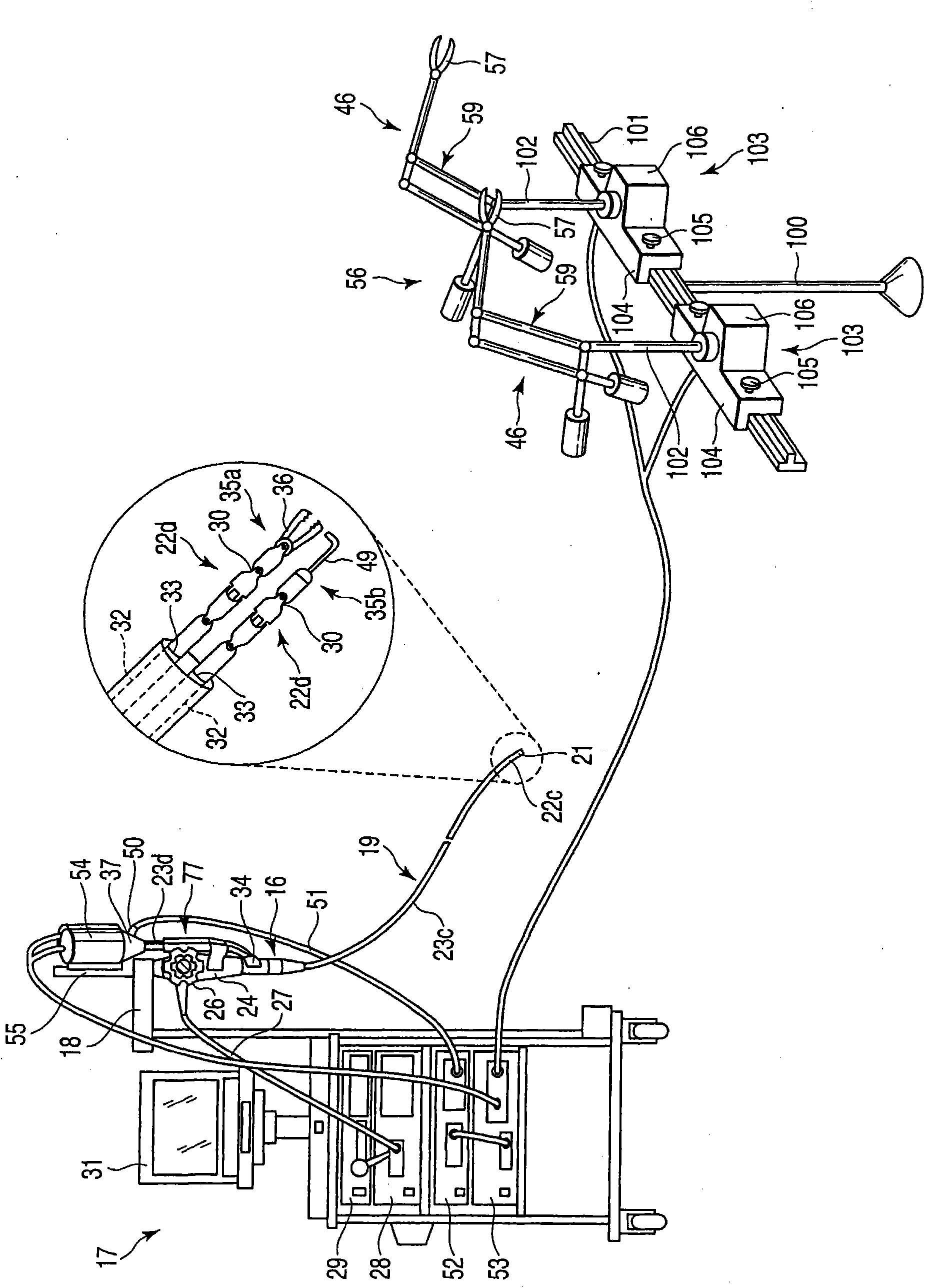
[0044] refer to figure 1 with figure 2 The general configuration of the medical system will be described.

[0045] As for the endoscope 16 as an insertion device, the base end portion of the endoscope 16 is supported by an endoscope support arm 18 provided on a trolley 17 . The endoscope 16 has an elongated insertion portion 19 to be inserted into a body cavity. In the insertion part 19, a distal rigid part 21, a bendable endoscope bending part 22c, and a long and flexible endoscope flexible tube part 23c are continuously provided from the distal end toward the proximal end. The operation part 24 operated by the operator is connected to the base end part of the insertion part 19. As shown in FIG. A bending operation knob 26 and the like for bending the endoscope bending...


PUM


Abstract

A medical system includes an insertion device to be inserted into a body cavity and including a channel extending between a distal end portion of the insertion device and a proximal end portion thereof and a proximal end opening portion connected with a proximal end portion of the channel, a treatment device to be inserted into the channel from the proximal end opening portion and to be inserted through the channel, and including an actuating portion provided at a distal end portion of the treatment device, a coupling portion provided at a proximal end portion of the treatment device, and a transmitting portion extending between the actuating portion and the coupling portion and to transmit a driving force applied to the coupling portion to the actuating portion, a driving device includinga coupling accepting portion to be coupled with the coupling portion and a driving mechanism to drive the coupling portion coupled with the coupling accepting portion, and a guide mechanism includinga guide member to be arranged between the coupling portion coupled with the coupling accepting portion and the proximal end opening portion, to support and guide the transmitting portion between thecoupling portion coupled with the coupling accepting portion and the proximal end opening portion, and harder than the transmitting portion.

Description

technical field [0001] The present invention relates to a medical system that inserts a surgical device into a body cavity through a channel of an insertion device inserted into a body cavity, applies a driving force to a base end of the surgical device, and transmits the driving force to a front end of the surgical device through a transmission part. Action part to move the action part. Background technique [0002] A system for medical use is disclosed in US Patent Application Publication No. 2005 / 70757 specification. In this medical system, an endoscope is inserted into a body cavity, forceps are inserted into the body cavity from a forceps opening of the endoscope through a treatment instrument channel, and surgery is performed using the forceps. In the forceps, a grasping portion for grasping a living tissue and a long and flexible flexible tube portion are continuously provided from the distal end side toward the proximal end side. By manually advancing, retreating, ...

Claims


Application Information

Patent Timeline
Patent Type & Authority Applications(China)
IPC IPC(8): A61B17/00A61B17/94A61B17/29A61B1/005A61B18/12
CPCA61B2019/2242A61B17/29A61B1/00133A61B2017/0034A61B2019/2276A61B19/22A61B1/018A61B2034/742A61B34/70A61B34/71
Inventor 重田健万寿和夫
Owner OLYMPUS CORP
Learn More