Automatic time control and pressure regulation scald apparatus

A time-adjusting and pressure-adjusting technology, applied in the direction of heating surgical instruments, etc., can solve the problems of changes in the pressure contact surface of the metal scalding head, uneven depth, affecting the research results, etc., to achieve accurate scalding time, steam pressure and temperature control, and shape. Consistent with size and good repeatability

Inactive Publication Date: 2009-11-11
童亚林
View PDF0 Cites 3 Cited by
  • Summary
  • Abstract
  • Description
  • Claims
  • Application Information

AI Technical Summary

Problems solved by technology

However, this type of equipment has the following disadvantages: after the burn time is up, the hot head will be manually removed, making it difficult to make consistent burn times for making multiple burn wound models; Manually controlled metal irons may vibrate during burns, especially when animals move, which will cause changes in the pressure of the metal iron and the contact surface with the skin. These unstable factors lead to the shape of the burn wound Irregular, uneven depth
The scalding time of the existing steam scalding equipment is controlled by manually cutting off the steam, and it is difficult to keep the scalding time consistent when making multiple scald wound models; in addition, the steam pressure of the existing steaming equipment cannot be adjusted according to needs and can only be adjusted at one time

Method used


Image

  • Automatic time control and pressure regulation scald apparatus
  • Automatic time control and pressure regulation scald apparatus
  • Automatic time control and pressure regulation scald apparatus

Examples


Example Embodiment

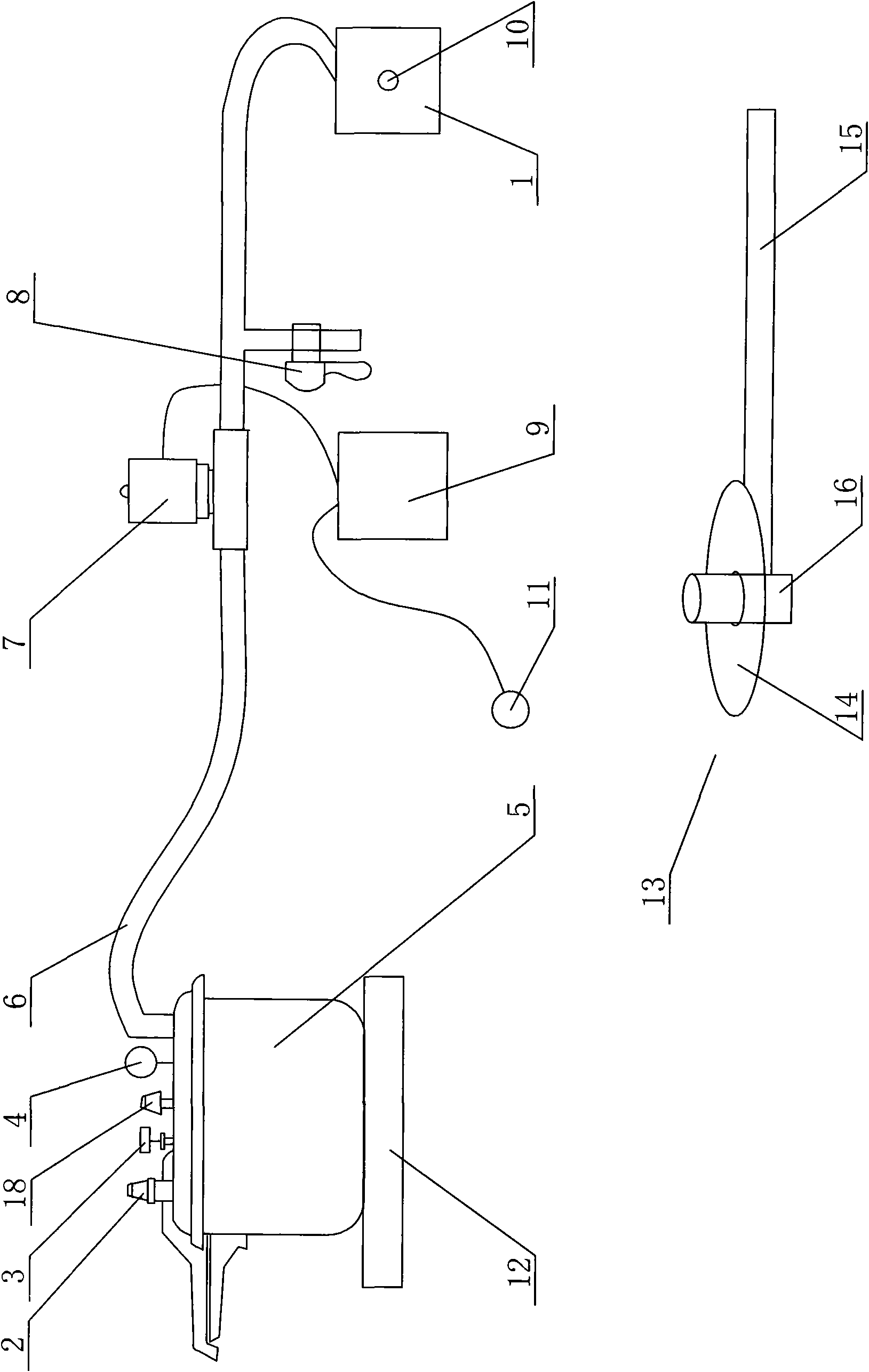
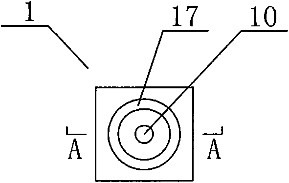
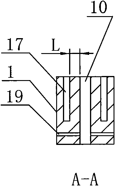
[0022] figure 1 In the illustrated embodiment, the automatic time-controlling pressure regulating scald instrument of the present invention includes an electromagnetic oven 12, a pressure cooker 5, a steam nozzle 1, a steam delivery pipe 6, an electromagnetic valve 7, a steam and water discharge valve 8, and a scald mold 13. The pressure cooker 5 is equipped with a manually adjustable steam pressure valve 2, a digital thermometer 3, a pressure gauge 4, and an original safety valve 18. The steam nozzle is made of foam. The center of the foam is provided with a steam hole 10 penetrating the foam, the diameter of which is smaller than the inner diameter of the steam delivery pipe 6; an annular groove 17 is opened on the periphery of the steam hole 10, which The depth is smaller than the depth of the steam hole 10, and its caliber is larger than the diameter of the steam hole. The distance between the inner side wall of the steam hole and the inner side wall of the annular groove is...


PUM


Abstract

The invention relates to a scald apparatus for producing a scald wound model of an animal, in particular to an automatic time control and pressure regulation scald apparatus. The scald apparatus comprises a vapour generator and a vapour spray head, wherein a pressure regulating valve, a thermometer and a pressure gauge are arranged on the vapour generator; and the vapour generator is communicated with the vapour spray head by a vapour conveying pipe, an electromagnetic valve and a vapour-water discharge valve are arranged on the path of the vapour conveying pipe, the vapour-water discharge valve is arranged between the electromagnetic valve and the vapour spray head, the electromagnetic valve is in circuit connection with a time controller, and the time controller is started by a time controller switch. For further improvement, the scald apparatus also comprises a scald mould which can effectively fix the formulated scald area of the animal. Compared with the prior art, the automatic time control and pressure regulation scald apparatus of the invention can accurately regulate the scald time, and can regulate and supervise the vapour pressure at real time; and the safety performance is high, the maneuverability is good, and the surface of scald wound produced by the automatic time control and pressure regulation scald apparatus has regular boundary, uniform shape, accurate depth and good repeatability.

Description

Technical field: [0001] The invention relates to a scald instrument for preparing animal scald wound models, in particular to an automatic time-controlled and pressure-regulated scald instrument. Background technique: [0002] Establishing a standard animal burn wound model is the basis and premise for carrying out burn wound repair research and evaluating drug efficacy. A standardized animal burn wound model means that the size, shape, and depth of the burn wound are made with high accuracy, consistency and repeatability. To make a standardized animal burn wound model requires that the burn (scald) wound instrument for making the model must be It has constant pressure and temperature, accurate burn time, and the production of the model will not be affected by the movement of the animal during the burn. The instrument should also be suitable for the production of scald wound models of various parts of small and medium-sized animals (such as rabbit ears, the side of the mouse...

Claims


Application Information

Patent Timeline
IPC IPC(8): A61B18/04
Inventor 童亚林
Owner 童亚林
Why Eureka
Try Eureka