
Passive-potential energy speed-controlling escape elevator for civil high-rise buildings

A high-rise building and potential energy technology, applied in the field of escape devices, can solve the problems of inability to passively transport rescue personnel and equipment, low life-saving efficiency, and different operations, so as to save additional capital, high life-saving efficiency, and enhance braking ability Effect

Inactive Publication Date: 2009-11-11
赵长飞
View PDF1 Cites 5 Cited by
  • Summary
  • Abstract
  • Description
  • Claims
  • Application Information

AI Technical Summary

Problems solved by technology

[0003] The purpose of the present invention is to solve the technical difficulties of different operations, numerous steps, low life-saving efficiency and inability to passively transport rescuers and equipment in the existing escape equipment, and to provide a simple operation, high life-saving efficiency and passive rescue rescue equipment. Passive potential energy speed control escape elevator for civil high-rise buildings with personnel and equipment

Method used


Image

  • Passive-potential energy speed-controlling escape elevator for civil high-rise buildings
  • Passive-potential energy speed-controlling escape elevator for civil high-rise buildings
  • Passive-potential energy speed-controlling escape elevator for civil high-rise buildings

Examples


Embodiment Construction

[0032] The present invention will be described in further detail below in conjunction with the accompanying drawings and embodiments.

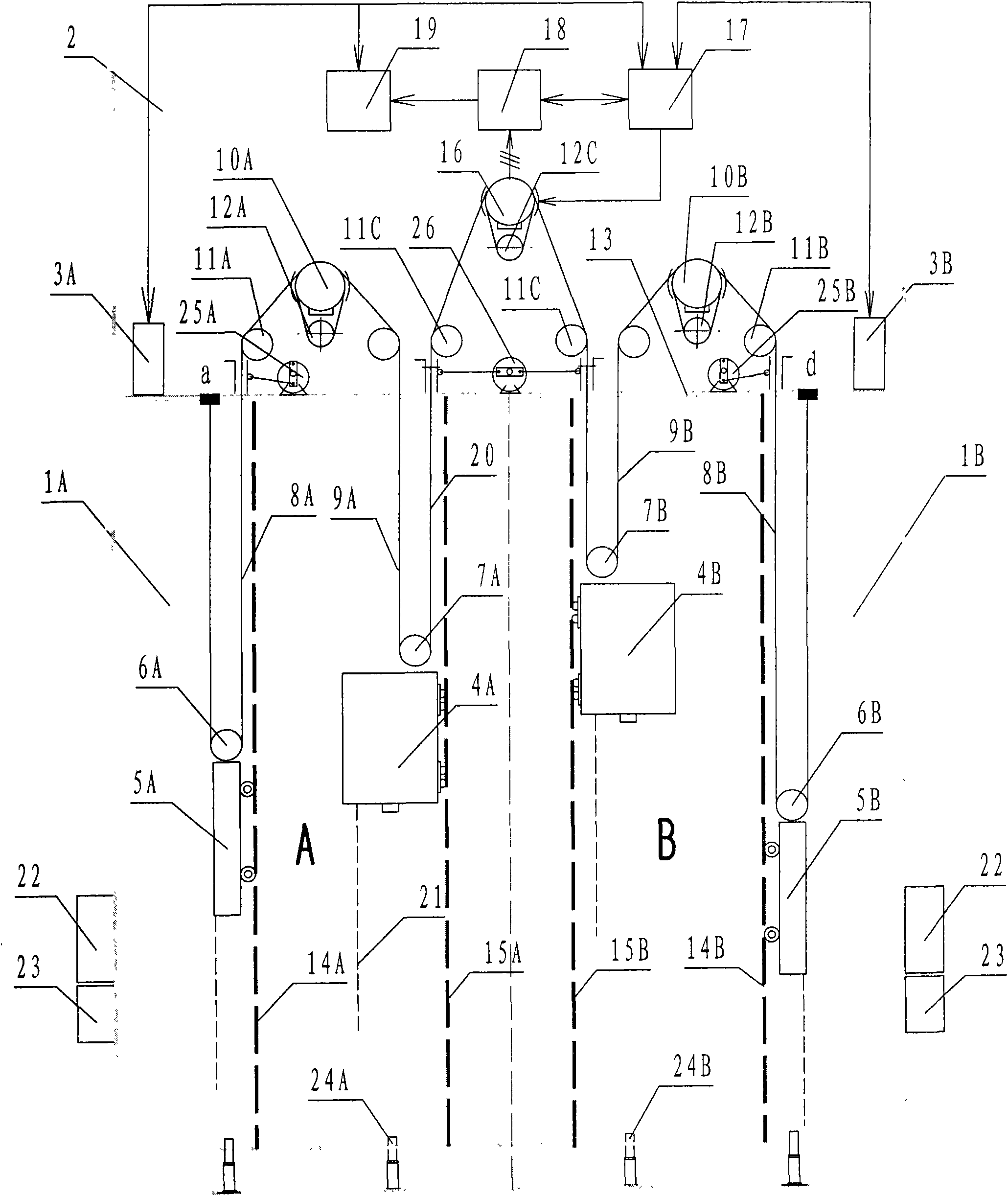
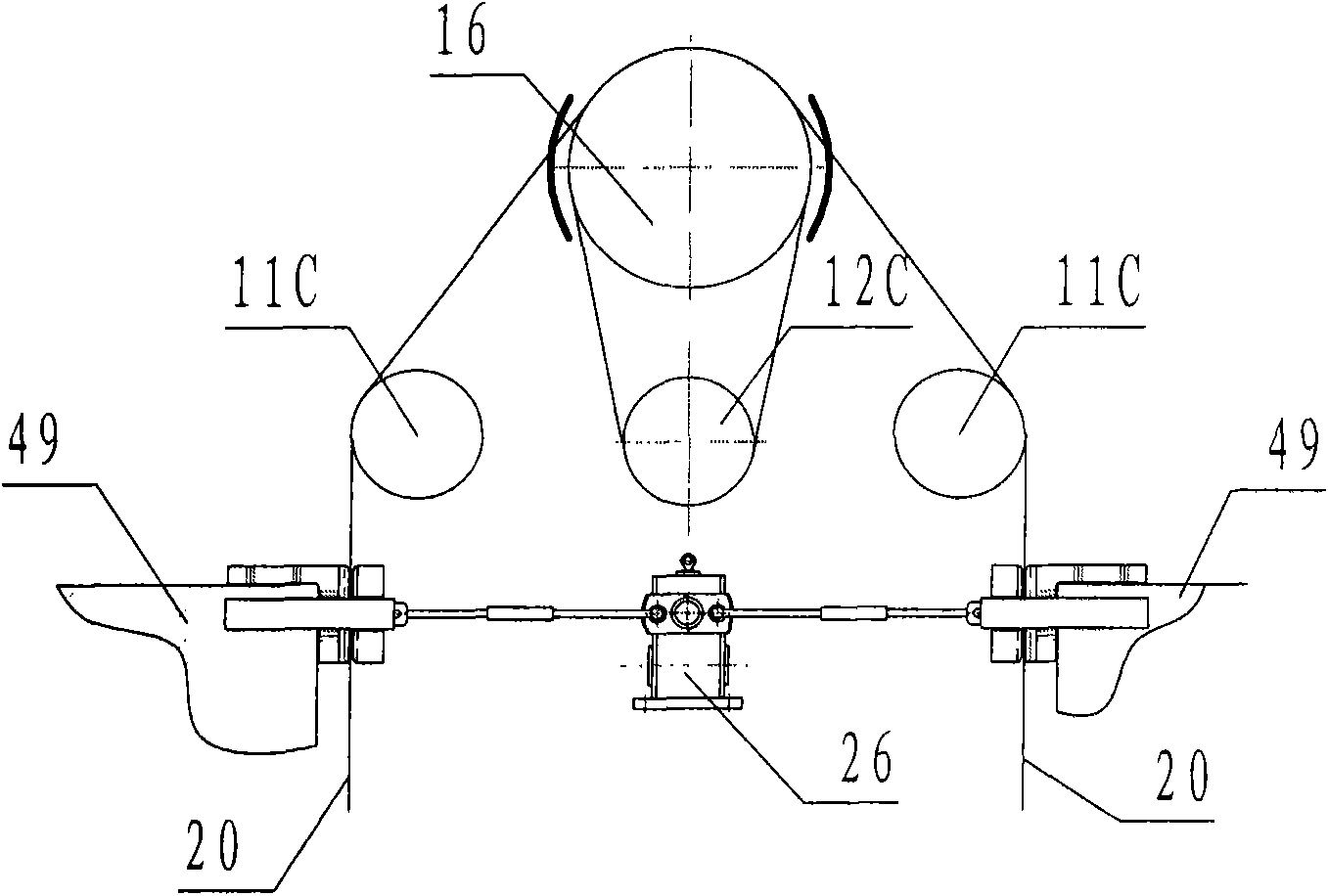
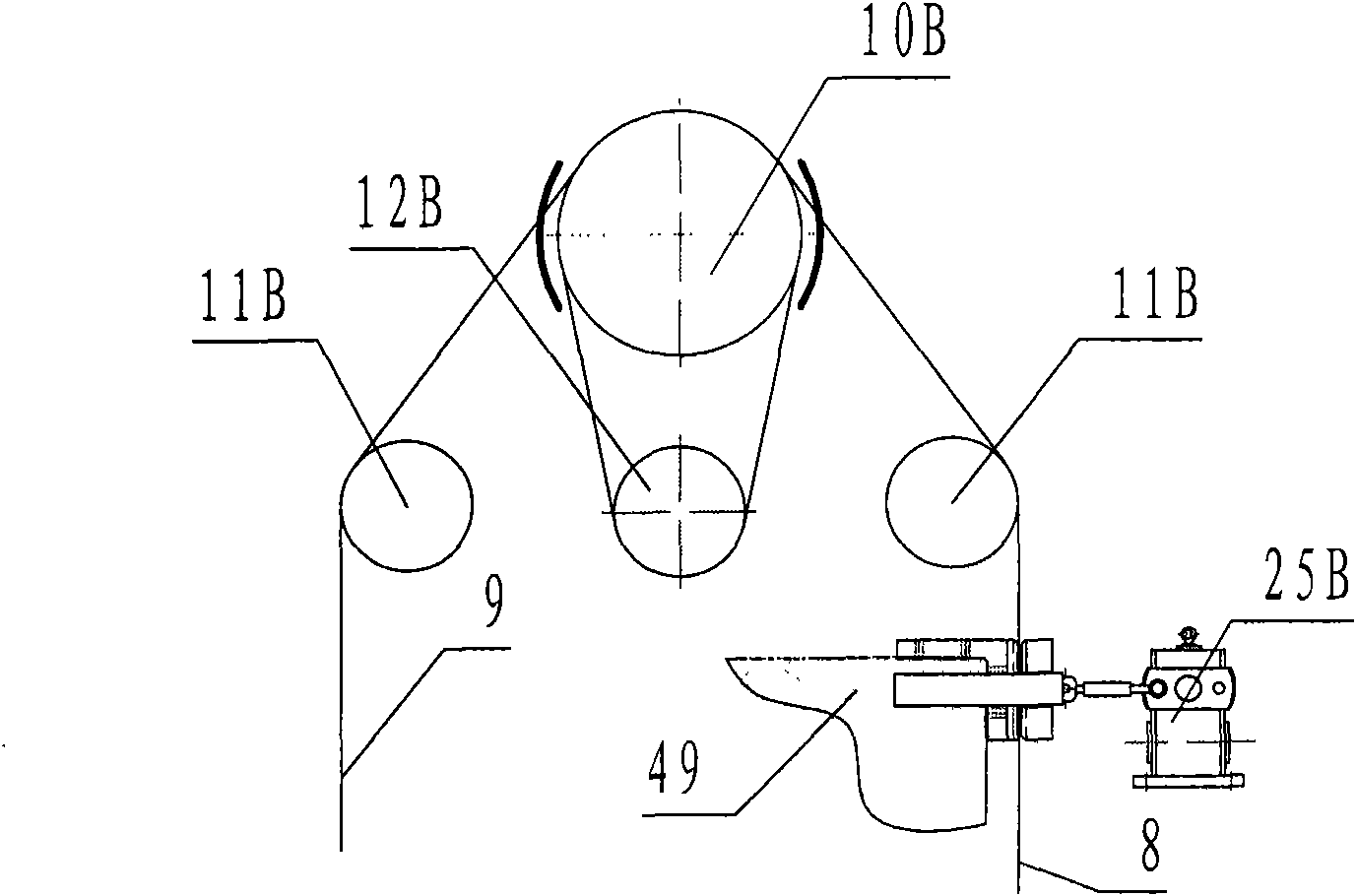
[0033] Such as figure 1 , figure 2 with image 3 As shown, the passive potential energy speed control escape elevator for civil high-rise buildings in this embodiment includes two passenger elevators arranged side by side in the elevator shaft, and one passenger elevator consists of car 4A, counterweight 5A, elevator traction machine 10A, counterweight traction rope 8A, car traction rope 9A, elevator controller 3A, car guide rail 15A and counterweight guide rail 14A, another passenger elevator consists of car 4B, counterweight 5B, elevator traction machine 10B, counterweight traction rope 8B, car traction rope 9B, elevator controller 3B, car guide rail 15B and counterweight guide rail 14B, wherein: two elevator traction machines 10A, A potential energy speed control device is set between 10B, and the potential energy traction rope 20 is ar...


PUM


Abstract

The invention relates a passive-potential energy speed-controlling escape elevator for civil high-rise buildings, which mainly solves the technical difficulties of the existing escape equipment, such as numerous operational steps, low rescue efficiency and impossibility of passively conveying succors. The passive-potential energy speed-controlling escape elevator for civil high-rise buildings comprises two elevators arranged in parallel in the elevator well; each elevator comprises a cage, a counterpoise, an elevator hoisting machine, counterpoise hoisting lines, cage hoisting lines, an elevator controller, cage guides and counterpoise guides. A potential-energy speed controlling device is arranged between two elevator hoisting machines in a one-well double-elevator engine room. The potential energy hoisting lines are arranged on a magnetic damping hoisting machine of the potential-energy speed controlling device. The potential energy hoisting lines are connected with the cage hoisting lines. A potential-energy line locking pliers is arranged under the beam pulley of the magnetic damping hoisting machine. A counterpoise line locking pliers is arranged under the beam pulley of the elevator hoisting machine. Two cages arranged on the two sides of the magnetic damping hoisting machine move to and fro under the gravitational potential energy of additional weight.

Description

technical field [0001] The invention relates to a passive potential energy speed control escape elevator for civil high-rise buildings. The escape device with the slow down function of the source. Background technique [0002] More and more high-rise buildings are built in modern cities, and it is not an isolated case that construction disasters cause mass death and mass injury. People have worked out multiple escape equipments for this reason, and all are people in distress from building high-rises with safety rope, belt or frame or box from window or roof one or several people once slowly drop to the ground. This type of escape equipment has different operations and many steps, and it is difficult for people in distress to correctly grasp it, failing to achieve the purpose of safe and quick escape. According to statistical data on the escape situation of building fires, the higher the floor, the greater the proportion of people choosing the most familiar elevator as the ...

Claims


Application Information

Patent Timeline
Patent Type & Authority Applications(China)
IPC IPC(8): B66B9/00B66B11/04B66B1/24
Inventor 赵长飞
Owner 赵长飞
Learn More