
Corrugated pipe joint

A bellows, main body technology, applied in the direction of pipes/pipe joints/pipe fittings, hose connection devices, mechanical equipment, etc.

Active Publication Date: 2009-11-11
SANKO CO LTD +1
View PDF1 Cites 6 Cited by
  • Summary
  • Abstract
  • Description
  • Claims
  • Application Information

AI Technical Summary

Problems solved by technology

However, in this joint, it is necessary to make the connection of the bellows more reliable or to further improve the airtightness, and there is room for further improvement in this point.

Method used


Image

  • Corrugated pipe joint
  • Corrugated pipe joint
  • Corrugated pipe joint

Examples


no. 1 approach

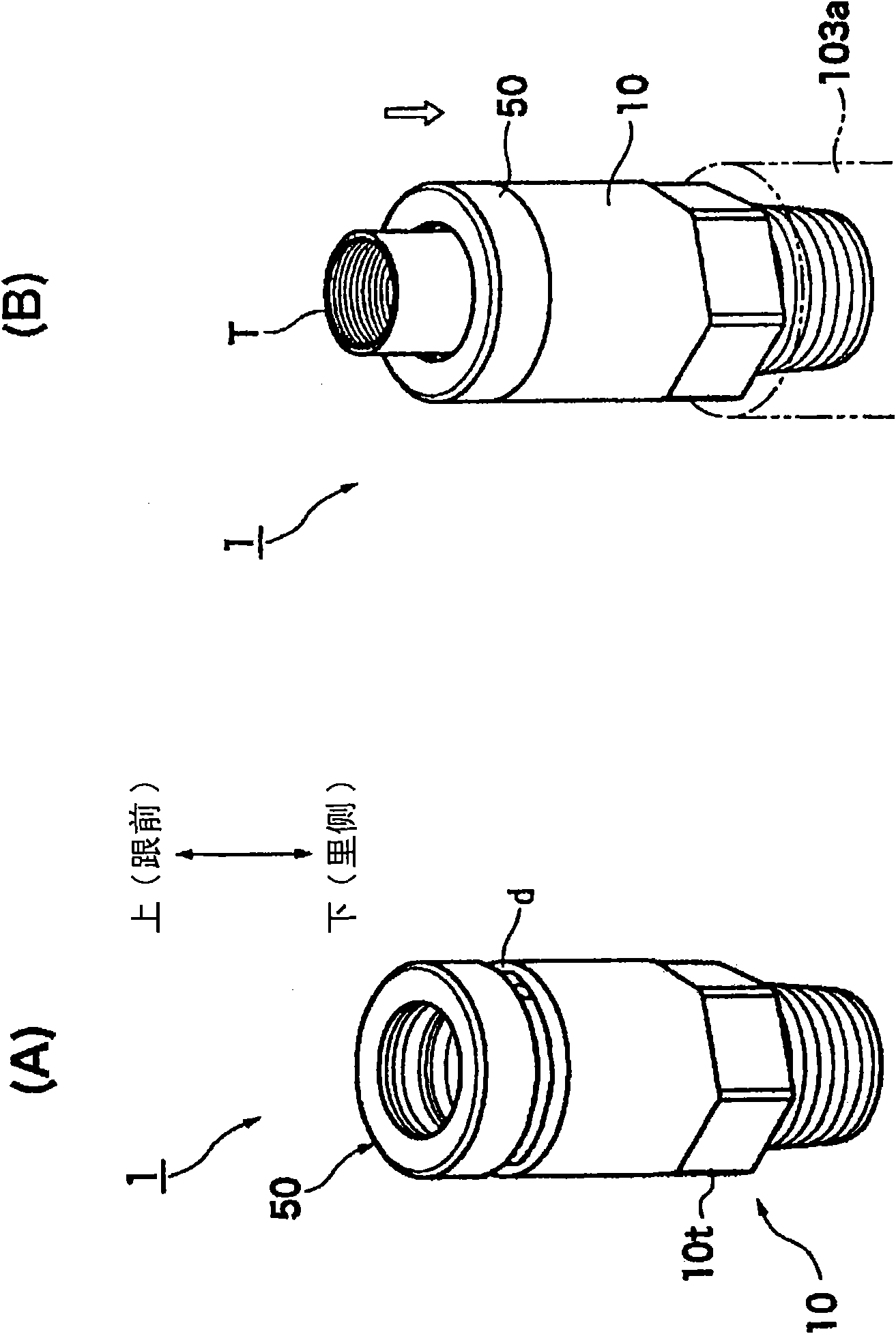
[0172] figure 1 It is an external perspective view explaining the outline of the bellows joint according to the first embodiment of the present invention, figure 1 (A) is a diagram showing the initial state of the joint, figure 1 (B) shows the final state of the joint (construction completion state of bellows insertion).

[0173] In addition, in the following description, unless otherwise specified, "up and down" means figure 1 In the direction indicated by the middle arrow. "Front" indicates the upper side in the figure (root side of the corrugated tube), and "rear side" indicates the lower side in the figure (front side of the corrugated tube).

[0174] First, the outline of the bellows joint 1 will be described.

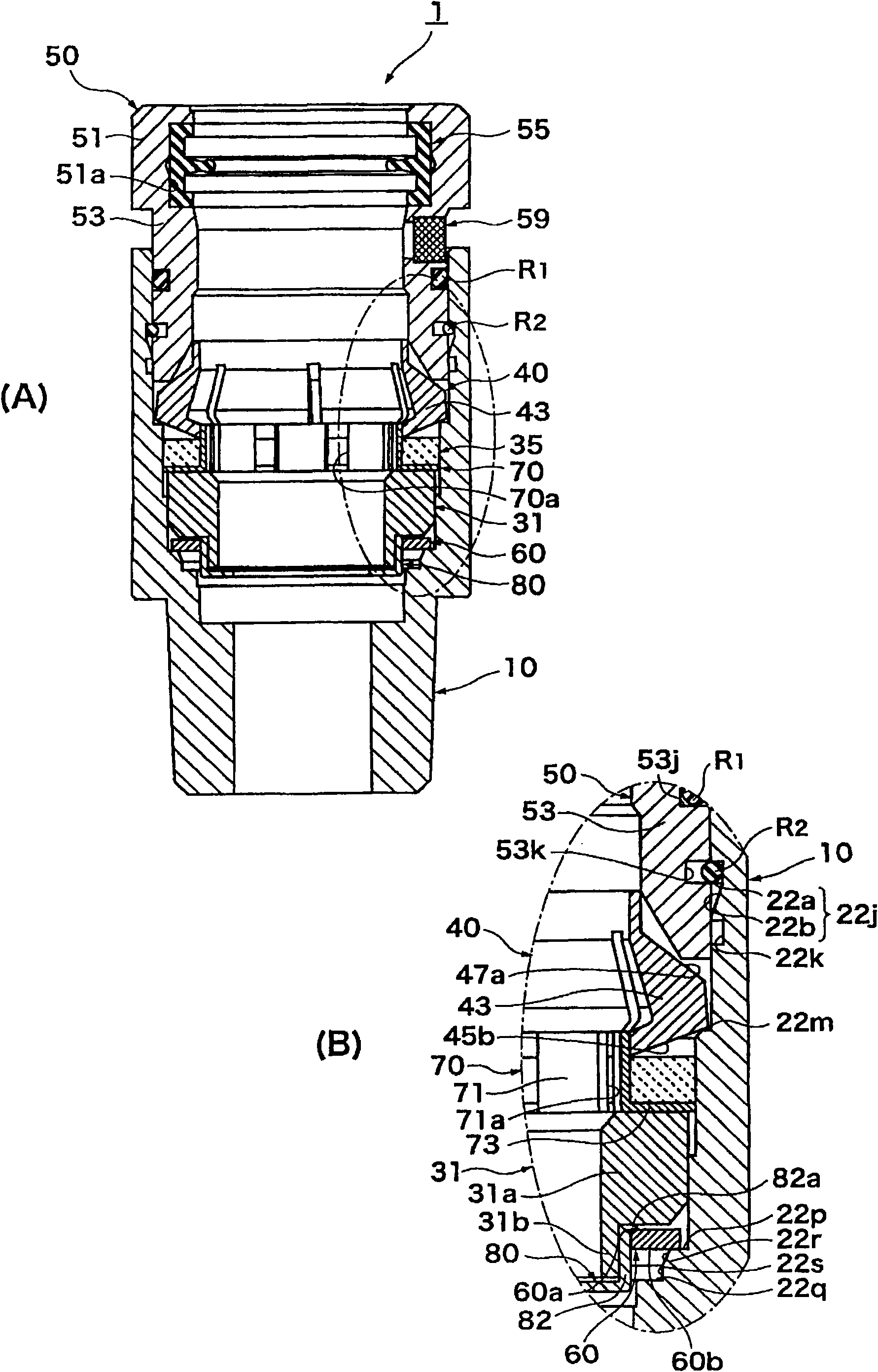
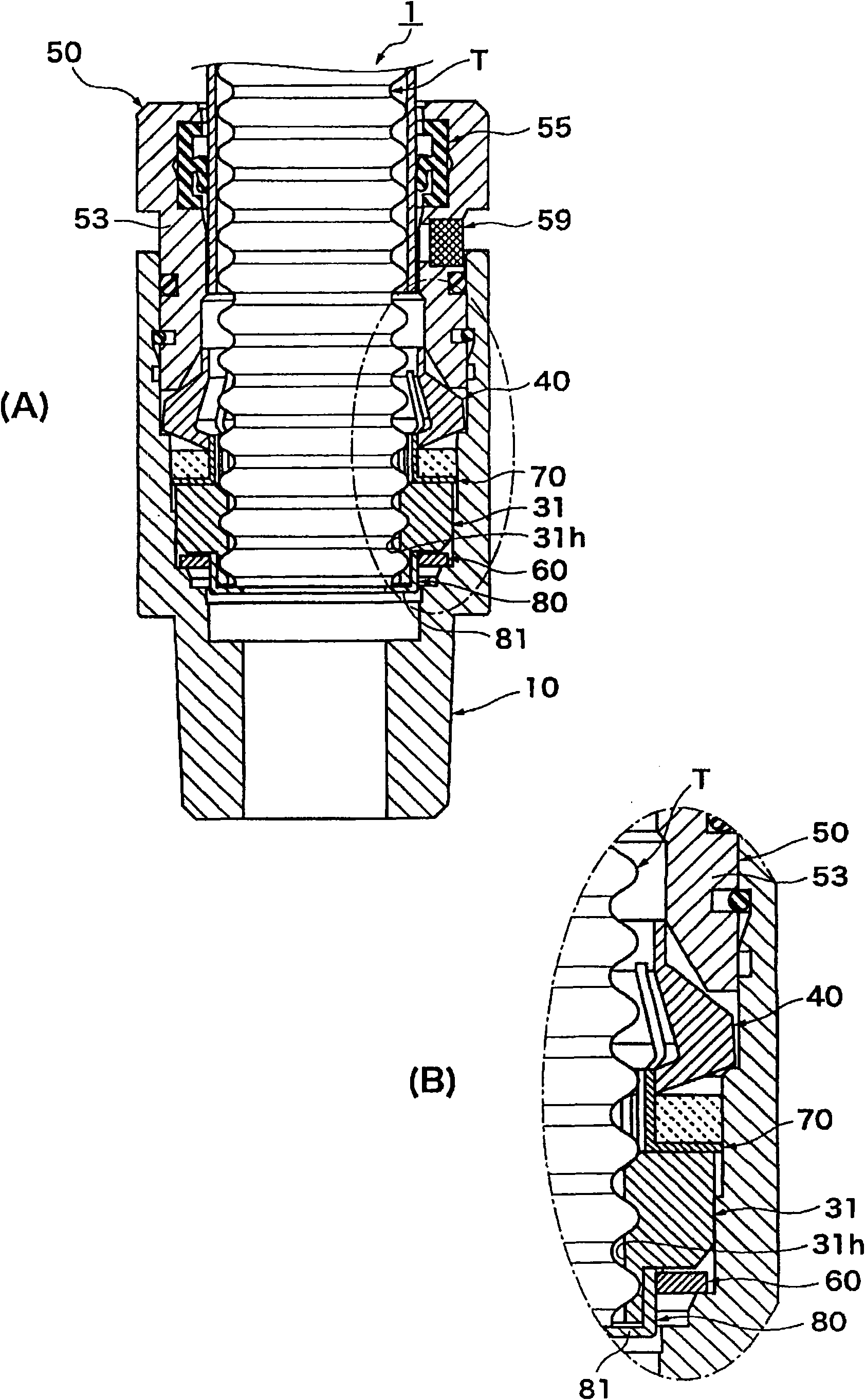
[0175] The bellows fitting 1, such as figure 1 (A) shows a cylindrical joint main body 10 in which various components (not shown in the figure) are arranged inside (details will be described later), and a retainer press cylinder 50 provided so as to be s...


PUM


Abstract

The invention relates to a corrugated pipe joint capable of securely connecting a corrugated pipe with a simple operation and capable of keeping a proper air-tight sealing state. In the corrugated pipe joint 1, a cylindrical joint main body 10 having an inner hole 11 into which a corrugated pipe T having annular furrows and ridges on its outer circumference is inserted, an air-tight packing 31, arranged in a joint main body inner hole, for tightly contacting with an outer circumferential surface of the corrugated pipe, a retainer 40, arranged in a joint main body inner hole, having a claw 43, of which diameter is enlargeable and contractable, engaging with an annular furrow part of the corrugated pipe when its diameter is contracted and a retainer pressing sleeve 50 for sliding in a rear direction and pressing the retainer to contract so that the claw of the retainer engages with the annular furrow part of the corrugated pipe. The retainer pressing sleeve is prevented from sliding in the joint main body inner hole in the rear direction till a tip end of the corrugated pipe reaches a predetermined position at a rear part of the joint main body inner hole.

Description

technical field [0001] The present invention relates to a bellows joint for connecting a bellows-shaped bellows to a gas pipe (steel pipe) or the like. In particular, it relates to a bellows joint capable of reliably connecting bellows with simple operations and ensuring a good airtight state. Background technique [0002] Figure 17 It is a diagram schematically showing an example of gas piping of a building. [0003] In this piping example, a gas counter (gas meter) 110 is installed outside the building 100, and a connecting portion (a three-way pipe) is provided in the middle of a gas pipe (steel pipe) 103 extending from the gas counter 110 toward the building 100 side. )) 103a. The end of the corrugated tube T is connected to the connecting portion 103 a via the corrugated tube joint 101 . The opposite end of the bellows T is connected to the gas socket 105 . Gas equipment 107 such as a gas heater is connected to the gas socket 105 via, for example, a rubber tube 106...

Claims


Application Information

Patent Timeline
Patent Type & Authority Applications(China)
IPC IPC(8): F16L33/22
Inventor 五十岚和忠内海洋一石部文和猪谷崇明荒木悟
Owner SANKO CO LTD
Learn More