Liquid crystal display device and driving method thereof

A technology of a liquid crystal display device and a driving method, which is applied to static indicators, nonlinear optics, instruments, etc., can solve problems such as coupled electrical coupling interference and affect image display quality, and achieve the effect of eliminating coupling interference and improving image display quality

Inactive Publication Date: 2010-12-29
INNOCOM TECH (SHENZHEN) CO LTD +1
View PDF4 Cites 0 Cited by
  • Summary
  • Abstract
  • Description
  • Claims
  • Application Information

AI Technical Summary

Problems solved by technology

[0014] In order to solve the problem that the coupling electricity of the liquid crystal display device in the prior art is prone to coupling interference and affect the image display quality, it is necessary to provide a liquid crystal display device that can eliminate the coupling interference of the coupling capacitance and improve the image display quality.

Method used


Image

  • Liquid crystal display device and driving method thereof
  • Liquid crystal display device and driving method thereof
  • Liquid crystal display device and driving method thereof

Examples


Embodiment Construction

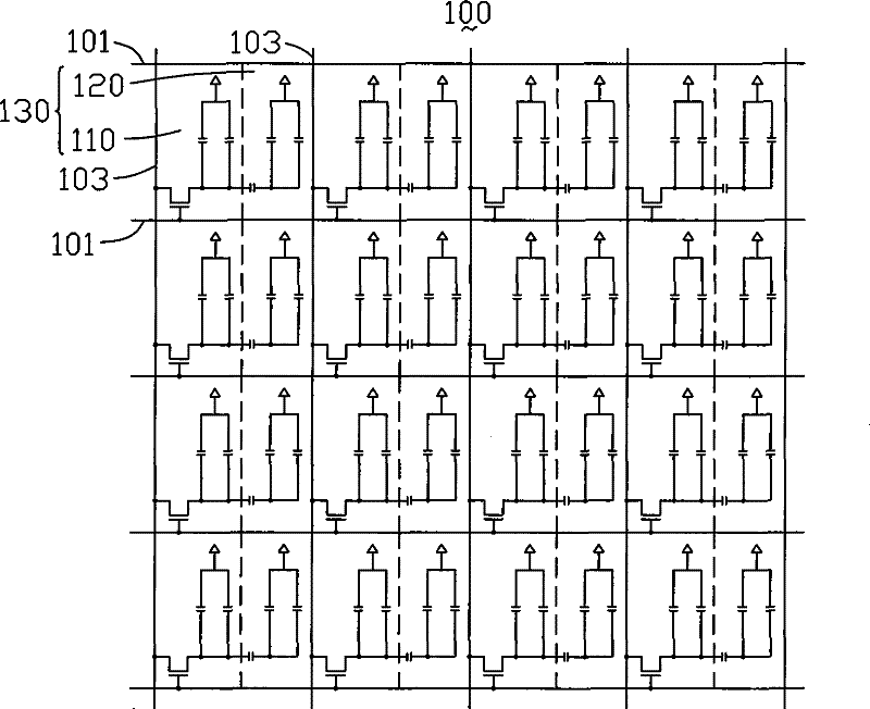
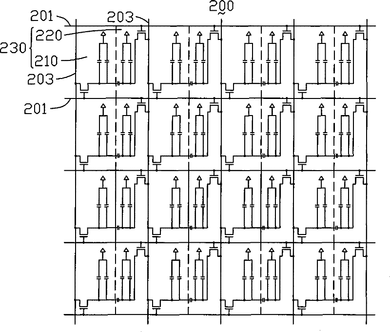
[0024] See image 3 , Is a schematic diagram of a preferred embodiment of the liquid crystal display device of the present invention. The liquid crystal display device 200 includes N rows of scan lines 201 that are parallel to each other, M columns of data lines 203 that are parallel to each other and intersect with the scan lines 201 perpendicularly and insulatedly, and a common electrode 207. The smallest rectangular area formed by the intersection of the N rows of scan lines 201 and the M columns of data lines 203 defines a plurality of pixel units 230. Among them, N=1, 2, 3, ..., n-1, n, n+1, ..., M=1, 2, 3, ... m- 1, m, m+1,..., n and m are all natural numbers greater than 3.

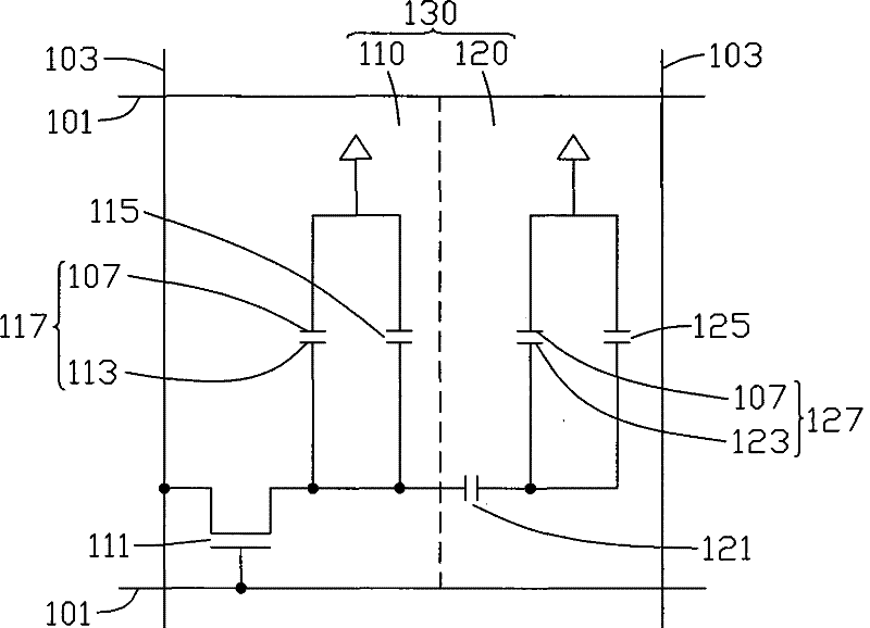
[0025] See Figure 4 , Figure 4 Yes image 3 An enlarged schematic diagram of a pixel unit 230 of the liquid crystal display device 200 is shown. The pixel unit 230 includes a first sub-pixel unit 210 and a second sub-pixel unit 220. The first sub-pixel unit 210 includes a first thin film transist...


PUM


Abstract

The invention relates to a liquid crystal display device which comprises a plurality of scanning lines, a plurality of data lines and a plurality of pixel units defined by minimum areas and formed by the scanning lines and the data lines, wherein each pixel unit comprises a first sub-pixel unit and a second sub-pixel unit; the first sub-pixel unit comprises a first thin film transistor and a firstpixel electrode; the second sub-pixel unit comprises a second thin film transistor, a coupling capacitor and a second pixel electrode; grids of the first thin film transistors and the second thin film transistors are respectively connected with a scanning line, and source electrodes are respectively connected with a data line; drain electrodes of the first thin film transistors are connected withthe first pixel electrodes and connected with the second pixel electrodes through the coupling capacitors; and drain electrodes of the second thin film transistors are connected with the second pixelelectrodes and connected with the first pixel electrodes through the coupling capacitors. The liquid crystal display device and a driving method thereof can eliminate the coupling interference of thecoupling capacitors so as to improve the image display quality.

Description

Technical field [0001] The invention relates to a liquid crystal display device and a driving method thereof. Background technique [0002] The liquid crystal in the liquid crystal display device itself does not have light-emitting characteristics, and it uses an electric field to control the twisting of liquid crystal molecules to achieve the passage or non-passing of light, thereby achieving the purpose of display. The liquid crystal driving mode of the traditional liquid crystal display device is a twisted line mode, but its viewing angle range is relatively narrow, that is, when viewing the picture from different angles, different display effects will be observed. In order to solve the problem of the relatively narrow viewing angle of the twisted line mode liquid crystal display device, the industry proposes a four-domain vertical alignment type liquid crystal display device. The "<" shaped protrusions and grooves divide each pixel unit into four regions, and the orientati...

Claims


Application Information

Patent Timeline
Patent Type & Authority Patents(China)
IPC IPC(8): G02F1/1362G09G3/36
Inventor 张月泙洪肇逸柳智忠
Owner INNOCOM TECH (SHENZHEN) CO LTD
Why Eureka
Try Eureka