Mouse-cage type tapered rotor electromotor

A conical rotor and motor technology, applied in the field of motors, can solve the problems of increasing the cost of motor materials, increasing the size of the motor, and consuming energy, and achieve the effects of compact structure, high starting torque, and high economy

Inactive Publication Date: 2009-11-11
无锡市宏泰电机股份有限公司
View PDF0 Cites 5 Cited by
  • Summary
  • Abstract
  • Description
  • Claims
  • Application Information

AI Technical Summary

Problems solved by technology

[0002] Commonly used motor brakes are mostly installed with a brake disc on the main shaft of the motor. The brake disc itself will increase the moment of inertia of the motor, so that the motor may consume extra energy during operation, and because the brake disc itself It has a certain imaginary structure and occupies a relatively large space, which will increase the size of the motor virtually, consume more materials, and increase the material cost of manufacturing the motor

Method used


Image

  • Mouse-cage type tapered rotor electromotor

Examples


Embodiment Construction

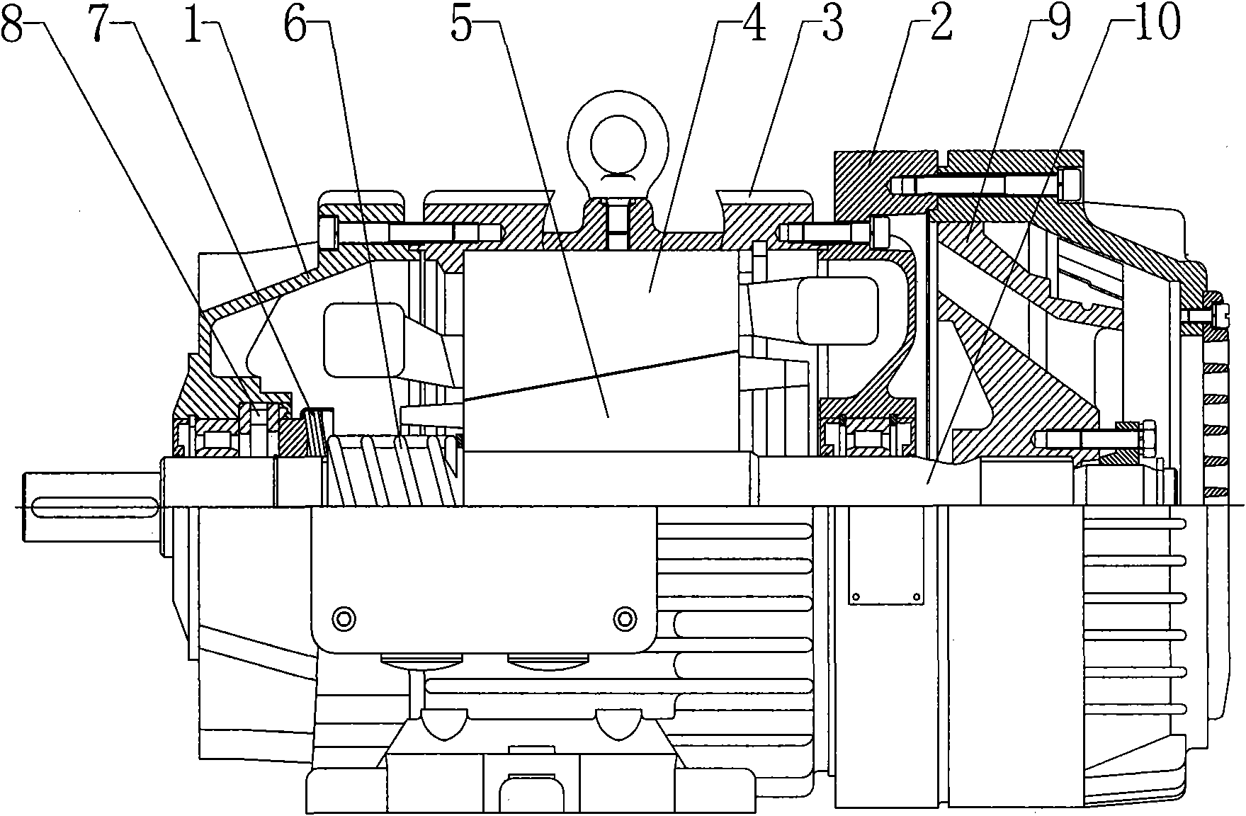
[0014] like figure 1 As shown, a squirrel-cage conical rotor motor described in the embodiment of the present invention includes a front end cover 1, a rear end cover 2, a casing 3 and a main shaft 10 passing through the casing 3, and a The stator 4 and the rotor 5, the rotor 5 is installed on the main shaft 10, the rotor 5 is conical, and the stator 4 is also matched with the rotor 5 to form a conical inner cavity, and the mating surface of the rotor 5 and the stator 4 is made into a friction surface .

[0015] A further design of the motor is that a brake spring 6 is provided on the motor shaft 10 at the front end of the rotor 5 , and the other end of the brake spring 6 is connected to the front end cover 1 .

[0016] The further design of the motor is that the brake spring 6 is connected to the front end cover 1 through a butterfly spring group 7, and a thrust cylindrical roller bearing 8 is arranged in the middle.

[0017] A further design of the electric motor is that a...


PUM


Abstract

The invention relates to a mouse-cage type tapered rotor electromotor, and the main design of the electromotor comprises that: an inner cavity of a stator and the surface of a rotor of the electromotor are tapered; the tapered rotor is simultaneously used as a brake. After a triphase winding of the stator is connected with a power supply, an axial magnetic pull force is generated to allow the rotor to generate axial movement; an axial braking spring is drawn; and the tapered rotor is pushed to enable the normal operation of the electromotor; when the electromotor is needed to be stopped, the power supply of the electromotor is powered off; and then the axial magnetic pull force disappears; under the action of resilience of the spring, the tapered rotor rapidly brakes to allow the rotor to stop rotating immediately, thereby realizing the function of rapid braking.

Description

technical field [0001] The invention relates to a motor, in particular to a conical rotor motor. Background technique [0002] Commonly used motor brakes are mostly installed with a brake disc on the main shaft of the motor. The brake disc itself will increase the moment of inertia of the motor, so that the motor may consume extra energy during operation, and because the brake disc itself It has a certain imaginary structure and occupies a relatively large space, which will virtually increase the size of the motor, consume more materials, and increase the material cost of manufacturing the motor. Contents of the invention [0003] The purpose of the present invention is to provide a squirrel-cage conical rotor motor. Commonly used motors adopt a brake structure to increase the size of the motor and consumables, and consume extra energy. [0004] The purpose of the present invention is to realize through the following technical solutions: [0005] A squirrel-cage conical ...

Claims


Application Information

Patent Timeline
IPC IPC(8): H02K7/12
Inventor 魏秋湘
Owner 无锡市宏泰电机股份有限公司
Why Eureka
Try Eureka