Compressor device, as well as the use of such an assembly

A technology for compressors and compressor rotors, used in mechanical equipment, machines/engines, liquid fuel engines, etc., can solve problems such as a large amount of energy loss, leakage of rotor shaft seals, and easy wear of contact seals, achieving high energy Efficiency, avoidance of leakage, avoidance of frictional losses

Active Publication Date: 2014-12-17
ATLAS COPCO AIRPOWER NV
View PDF7 Cites 5 Cited by
  • Summary
  • Abstract
  • Description
  • Claims
  • Application Information

AI Technical Summary

Problems solved by technology

[0009] If the above measures are not taken, the drive motor will not be able to generate sufficient torque during starting, or the supply network will not be able to supply the starting current necessary to generate a higher starting torque
[0010] An important disadvantage of these known compressor installations is that a large amount of energy is lost with the loss of compressed air already stored in the pressure vessel and the screw compressor after the screw compressor has stopped
[0027] The application of a sealed inlet valve would thus entail a high risk of leakage in the rotor shaft seal after the screw compressor has stopped
[0028] Furthermore, when the screw compressor is under pressure, restarting the screw compressor is accompanied by high frictional losses, so that the seals may be easily damaged
[0029] Other disadvantages of known compressor installations relate to the sealing itself of the screw compressor
[0030] The rotor shaft of the involved compressor rotor turns at a very high speed, so that this type of seal creates a huge energy loss during the operation of the screw compressor, which leads to a decrease in the efficiency of the screw compressor
[0031] In addition, this "contact seal" is subject to wear and is very prone to leakage if not installed carefully
[0032] Another aspect that needs to be improved on known compressor installations of this type as described above is that both the drive motor and the screw compressor must be lubricated and cooled, usually comprising separate systems , so they are not compatible with each other, which would require many different types of lubricants and / or coolants and thus be complex or expensive
[0033] Furthermore, in such known compressor installations with a separate cooling system for cooling the drive motor and the compressor rotor separately, it is possible to recover in an optimal way the lost heat stored in the coolant sex is not fully realized

Method used


Image

  • Compressor device, as well as the use of such an assembly
  • Compressor device, as well as the use of such an assembly

Examples


Embodiment Construction

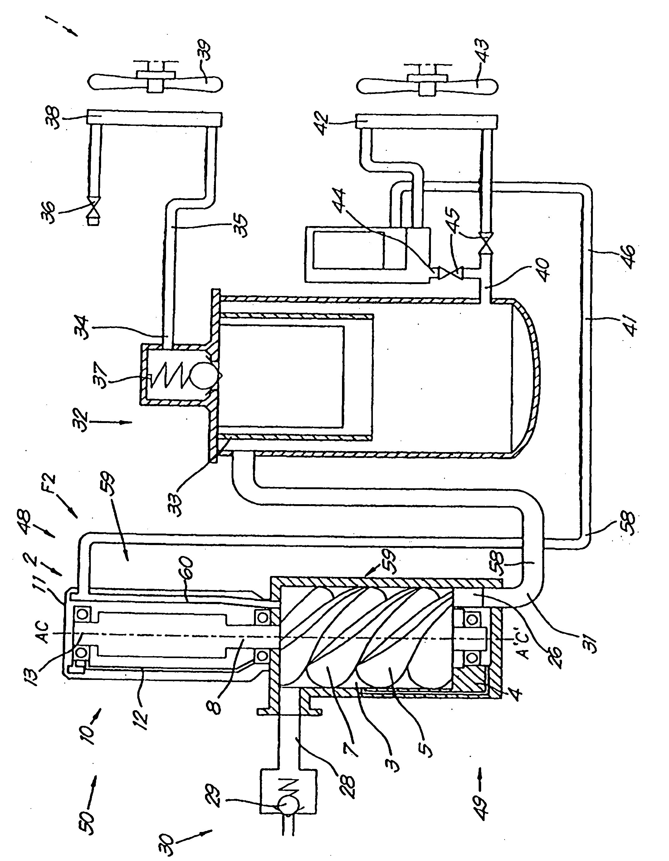
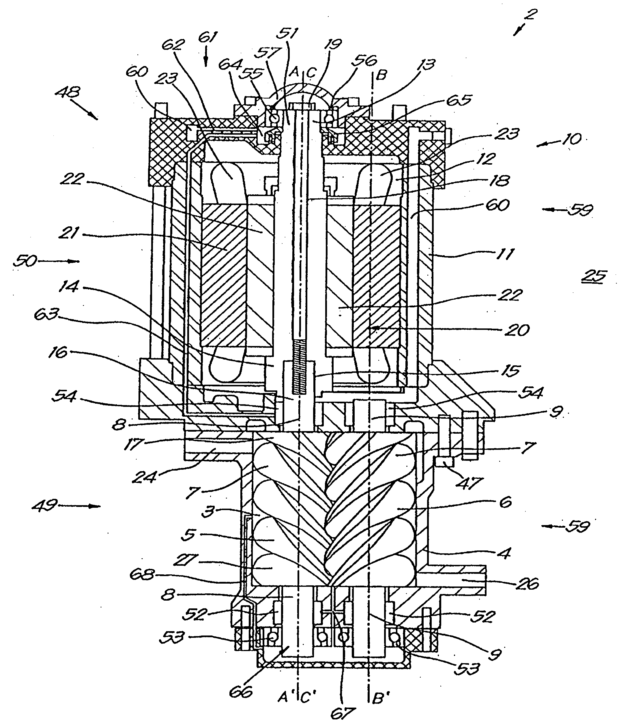
[0067] A compressor device 1 according to the invention such as figure 1 As shown, the compressor equipment first includes a screw compressor 2, which is figure 2 As shown in more detail in , the screw compressor 2 has a compression chamber 3 formed by a compression housing 4 .

[0068] In the compression chamber 3, a pair of meshed compression rotors, more specifically, a first compressor rotor 5 and a second compressor rotor 6, are rotatably installed.

[0069] These compressor rotors 5 and 6 have a helical profile 7 which surrounds and is connected to the rotor shafts of the compressor rotors 5 and 6 in question, respectively rotor shaft 8 and rotor shaft 9.

[0070] The rotor shaft 8 thus extends along a first axial direction AA' and the rotor shaft 9 extends along a second axial direction BB'.

[0071] Furthermore, the first axis direction AA' and the second axis direction BB' are parallel to each other.

[0072] In addition, the screw compressor is provided with a d...


PUM


Abstract

Compressor device that is at least provided with a screw compressor (2) with a compression chamber (3) that is formed by a compression housing (4), with a drive motor (10) that is provided with a motor chamber (12) formed by a motor housing (11) and with an outlet (26) for the discharge of compressed air that is connected to a pressure vessel (32) via an outlet pipe (31), whereby the compression housing (4) and the motor housing (11) are connected directly to one another to form a compressor housing (48), whereby the motor chamber (12) and the compression chamber (3) are not sealed off from one another and whereby the outlet pipe (31) between the pressure vessel (32) and the screw compressor (2) is free of closing means.

Description

technical field [0001] The invention relates to a compressor device. [0002] More specifically, the present invention relates to a compressor device provided with at least the following elements: a screw compressor having a compression chamber formed by a compression housing, in which A pair of intermeshing compressor rotors is rotatably mounted; a drive motor is provided with a motor cavity formed by a motor housing, in which is rotatably mounted a motor for driving the two compressor rotors at least one motor shaft; an inlet of a screw compressor for supplying air; an outlet of a screw compressor for discharging compressed air, the outlet of said screw compressor being connected to a pressure vessel via an outlet line; the pressure vessel an air outlet for supplying compressed air from a pressure vessel to a device for use; and a control system for controlling the flow of one or more liquids or gases in a pneumatic device, the control system An inlet valve is provided at ...

Claims


Application Information

Patent Timeline
Patent Type & Authority Applications(China)
IPC IPC(8): F04C18/16F04C23/00F04C28/06
CPCF04C18/16F04C23/008F04C28/06F04C29/021F04C29/042F04C2240/30F04C29/045
Inventor A·J·F·德西隆
Owner ATLAS COPCO AIRPOWER NV
Why Eureka
Try Eureka