Parking pallet transverse moving drive device

A technology of parking tray and driving device, applied in the field of car parking, can solve the problems of inconvenient use and maintenance, hidden dangers, and high occurrence rate of power line failure, and achieve the effect of good safety and reliability

Inactive Publication Date: 2015-04-29
梁晓军
View PDF5 Cites 6 Cited by
  • Summary
  • Abstract
  • Description
  • Claims
  • Application Information

AI Technical Summary

Problems solved by technology

[0002] At present, the automobile industry is developing rapidly, followed by the rapid development of indoor parking technology. Among many indoor parking equipment, the technical solution of mechanical double-layer lifting and lateral movement is the most used. This technical solution requires each vehicle to need a Parking trays, power is provided on each parking tray, and the parking trays set on the ground parking space on the lower floor are driven by motors to move the rollers on the track to move left and right. Since the drive motor is set on the parking trays, each moving The parking tray needs to be equipped with a power cord. During use, the parking tray carries the power cord and moves left and right. The walking mode of this kind of parking tray carrying the power cord is not very reasonable in structure and technology, and the failure rate of the power cord carried is relatively high. High, it will cause inconvenience in use and maintenance, and there are certain hidden dangers in safety. Therefore, it is necessary to adopt a safer and more reliable technical solution to make the parking tray free from the power cord and bring convenience to the operator in use. , so the above situation needs to be solved in the application of indoor parking lot technology

Method used


Image

  • Parking pallet transverse moving drive device
  • Parking pallet transverse moving drive device
  • Parking pallet transverse moving drive device

Examples


Embodiment Construction

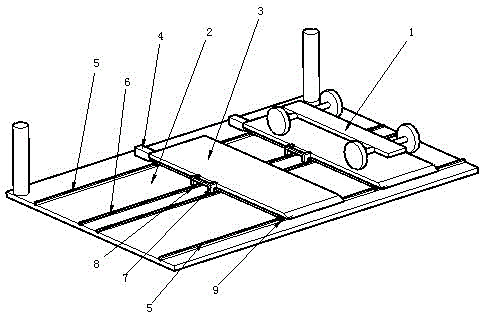
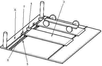
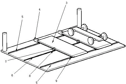
[0022] In the embodiment, there are three parking spaces (2) between the two concrete pillars, on which two traversing parking pallets (3) are arranged, and the DC motor (4) is installed on one side of the parking pallet (3) the end of the conductive track (6), the installation height of the conductive track (6) is lower than the height of the front and rear track (5), the conductive track (6) is insulated from the ground, and the brush holder (7) elastically connects the brush (8) to the conductive On the track (6), the output shaft of the DC motor (4) is connected to two rollers (9) on one side of the parking tray (3) through the transmission shaft, and the conductive track (6) is arranged on the parking space (2), and the conductive track The power supply voltage of (6) is a low-voltage direct current, and the direct current motor (4) is a brushed motor.

[0023] Such as figure 1 The schematic diagram of the double conductive rail drive device between the front and rear ra...


PUM


Abstract

Disclosed is a parking pallet transverse moving drive device. Rails are arranged on a ground parking space, parking pallets are arranged on the rails, rollers are arranged on the parking pallets, and each parking pallet is driven by a motor to bilaterally move on the rails. The parking pallet transverse moving drive device is characterized in that a direct-current motor is arranged on each parking pallet, a power supply brush carrier is arranged on the back surface of each parking pallet, a positive power supply brush and a negative power supply brush are arranged on each power supply brush carrier, a positive conducting rail and a negative conducting rail are bilaterally arranged on the ground parking space below the parking pallets, the positive power supply brush and the negative power supply brush slide on the two conducting rails to acquire direct-current voltage, each direct-current motor drives the corresponding parking pallet to bilaterally move on the rails, the device is used on the parking pallets needing transverse moving, the direct-current motors on the parking pallets acquire power from the positive conducting rail and the negative conducting rail on the ground parking space, the parking pallets do not need power wires, the failure rate of the parking drive device can be effectively decreased, and the running condition of the device is improved.

Description

technical field [0001] The invention relates to automobile parking technology, in particular to a parking tray traverse driving device. technical background [0002] At present, the automobile industry is developing rapidly, followed by the rapid development of indoor parking technology. Among many indoor parking equipment, the technical solution of mechanical double-layer lifting and lateral movement is the most used. This technical solution requires each vehicle to need a Parking trays, power is provided on each parking tray, and the parking trays set on the ground parking space on the lower floor are driven by motors to move the rollers on the track to move left and right. Since the drive motor is set on the parking trays, each moving The parking tray needs to be equipped with a power cord. During use, the parking tray carries the power cord and moves left and right. The walking mode of this kind of parking tray carrying the power cord is not very reasonable in structure ...

Claims


Application Information

Patent Timeline
Patent Type & Authority Applications(China)
IPC IPC(8): E04H6/22
CPCE04H6/22
Inventor 梁晓军
Owner 梁晓军
Why Eureka
Try Eureka