Method and device for determining failure in automatic switched optical network

A technology of automatic exchange and determination method, applied in the direction of selection device, selection device of multiplexing system, electromagnetic wave transmission system, etc., can solve the problems of jitter, system instability, service protection and recovery action, etc.

Inactive Publication Date: 2009-11-11
ZTE CORP
View PDF2 Cites 7 Cited by
  • Summary
  • Abstract
  • Description
  • Claims
  • Application Information

AI Technical Summary

Problems solved by technology

[0007] The channel alarm mechanism combines the channel alarm information of the node detected by the connection head node with the channel alarm information about the tail node sent by the connection tail node through messages to determine whether the fault of the connection occurs in the network, and then decides whether the connection is There is a fault; the Chinese patent application with the publication number CN101336004A discloses a method for judging a connection fault in an automatic switching optical network. The above-mentioned detection mechanism has a defect: if the channel alarms on the upper and lower service sides of the head and tail nodes are not very stable, it will cause The jitter of connection faults, that is, the frequent occurrence of connection faults and the disappearance of faults, thus frequently leads to the protection and restoration of services, resulting in the instability of the entire system; the Chinese patent application with the publication number of CN101164260A discloses a channel fault in an automatic switching optical network Although the mechanism is relatively stable and has good scalability, the network with shared rings needs to maintain the information of the shared rings of the entire network, and the judgment mechanism is relatively complicated, so it is difficult to implement

Method used


Image

  • Method and device for determining failure in automatic switched optical network
  • Method and device for determining failure in automatic switched optical network

Examples


Embodiment Construction
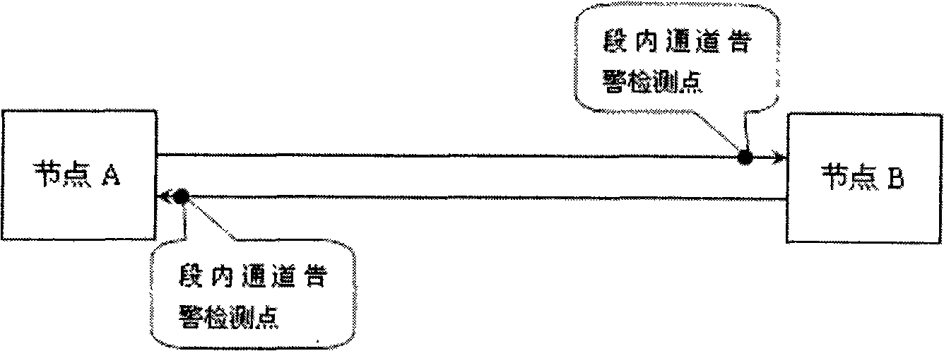
[0026] The basic idea of ​​the present invention is: adopt a connection fault confirmation mechanism combining channel alarm and multiplex section alarm, use the multiplex section alarm as the main judgment basis for connection failure, and combine the channel alarm on the line side of the tail node as an auxiliary basis. The advantage of this mechanism is that the channel alarms on the upper and lower service sides of the head and tail nodes are no longer used as the basis for judging connection failures. The invention does not have the problem of connection failure jitter, the system is more stable and reliable, and the processing logic is simple.

[0027] In order to make the object, technical solution and advantages of the present invention clearer, the present invention will be further described in detail by citing the following embodiments and referring to the accompanying drawings.

[0028] The fault determination principle on which the present invention is based is: if...


PUM


Abstract

The invention discloses a method for determining the failure in an automatic switched optical network, comprising the following steps of: generating multiplex section alarm in the connection to be detected; determining the failure of the connection to be detected if the passage alarm in the multiplex section exists; and determining the disappearing of the failure of the connection to be detected if the passage alarm disappears. The invention also discloses a device for determining failure in the automatic switched optical network, comprising a detection unit used for detecting the alarm of the connection to be detected and a determining unit; the determining unit is used for determining the failure of the connection to be detected when the detection unit detects that the multiplex section alarm and the passage alarm in the multiplex section exist and determining the disappearing of the failure of the connection to be detected when the detection unit detects the disappearing of the passage alarm. The method and the device does not generate vibration problem of the connection failure, the system is more stable and reliable and the processing logic is simple.

Description

technical field [0001] The invention relates to fault location and processing technology, in particular to a fault determination method and device in Automatic Switched Optical Network (ASON, Automatic Switched Optical Network). Background technique [0002] Compared with the traditional network, the ASON network has the following remarkable features: it is intelligent and can automatically configure the link, avoiding the time-consuming and laborious manual configuration in the traditional optical network; when the connection fails, it can combine the protection methods of the traditional network, such as multiplex section Protection, multiplex section sharing ring protection, subnet connection protection, etc., also has a unique protection and restoration method for the control plane, so it has greater self-healing capability and flexibility than traditional optical networks. Then, in the control plane, connection protection recovery is triggered by a connection failure. I...

Claims


Application Information

Patent Timeline
Patent Type & Authority Applications(China)
IPC IPC(8): H04B10/08H04J3/08H04Q11/00H04B10/075
Inventor 马志栋
Owner ZTE CORP
Why Eureka
Try Eureka