Light pipe clamp with smooth riveting base plate

A riveted and smooth technology, applied in the direction of pipes/pipe joints/fittings, pipe supports, mechanical equipment, etc., it can solve the problems of loose pipe clamps, insufficient stability and tightness of pipe clamps, causing danger, etc. Enhanced effect

Inactive Publication Date: 2009-11-18
王亚军
View PDF0 Cites 0 Cited by
  • Summary
  • Abstract
  • Description
  • Claims
  • Application Information

AI Technical Summary

Problems solved by technology

[0002] Pipe clamps are widely used in the laying of oil and gas pipelines in oil refining, chemical industry, metallurgy, mining, machinery and other industries. The pipe clamp is mainly composed of a pipe clamp cover plate, a bottom plate and one or more sets of screws and nuts. Through the clamping action of the screw and nut on the cover plate and the bottom plate, the pipe clamp is stressed and the pipe is clamped. A kind of pipe clamp, the force clamping on the pipe clamp is formed by the force of the screw nut between the pressure plate and the bottom plate, or the screw is directly fixed on the bottom plate, only through the nut on the cover plate It plays a fastening role to fix the pipe clamp. Since the pipe clamp is widely used in the laying of oil and gas pipelines in petrochemical, metallurgy, mining, machinery and other industries, it has a high performance in terms of stability, shock absorption, and noise reduction. Requirements, but the current pipe clamp's stabilizing device and the fastening method of the cover plate and the bottom plate to the pipe clamp have many defects in use. Only the ordinary screw and nut fastening method is used in actual production. The vibration of the pipeline makes the pipe clamp loose, directly affects the use of the pipeline, and even causes danger in production. At present, the development and research of the pipe clamp are mostly limited to the inner hole form of the pipe clamp. For example, the pipe clamp The parts are designed in the form of forks or a U-shaped notch is added to the pipe clamp, but the current research technology has failed to make a breakthrough in the research and innovation of the bottom plate and cover plate of the pipe clamp, especially in the stability of the pipe clamp. There are still many deficiencies in terms of fastness and

Method used


Image

  • Light pipe clamp with smooth riveting base plate
  • Light pipe clamp with smooth riveting base plate
  • Light pipe clamp with smooth riveting base plate

Examples


Embodiment Construction

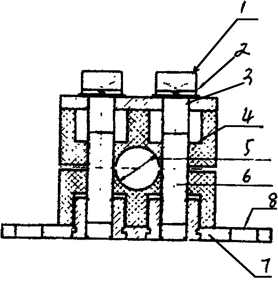
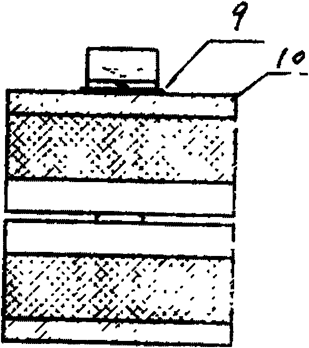
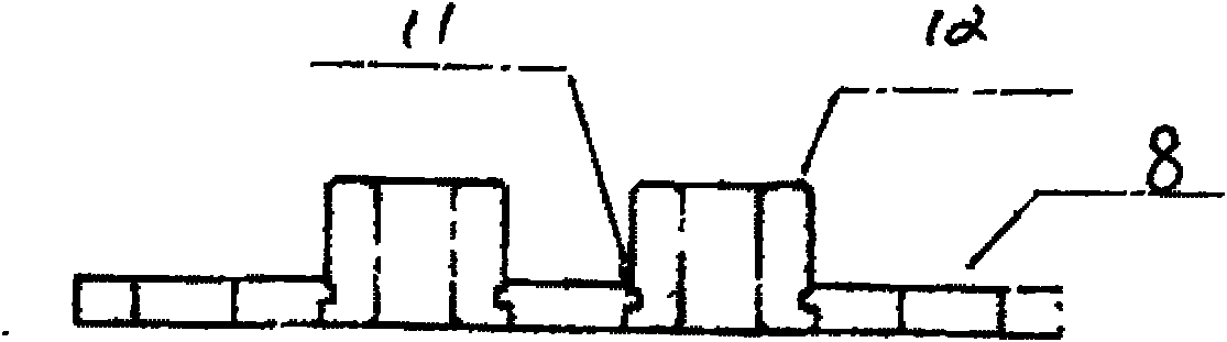
[0016] The specific implementation of the present invention will be further described below in conjunction with the accompanying drawings.

[0017] The smooth riveted floor light pipe clamp of the present invention includes a bolt 1, a spring pad 2, a cover plate bolt hole 3, a pipe clamp body 4, a pipe clamp hole 5, a pipe clamp body bolt hole 6, a riveted bottom plate 7, and a positioning hole 8 , flat washer 9, cover plate 10, anti-loosening bump 11, thread bubble 12, characterized in that the bolt 1 is sequentially inserted into the spring washer 2, flat washer 9, and the bolt 1 passes through the cover plate bolt hole 3, the pipe clamp After the body bolt hole 6, it is fixed on the riveted bottom plate 7 through the threaded bubble 12. The threaded bubble 12 is riveted together with the bottom plate through special pressure equipment and molds. The anti-loosening bump 11 is located between the bottom plate and the thread The riveting part of the bubble is used to prevent ...


PUM


Abstract

The invention relates to a light pipe clamp with a smooth riveting base plate, which comprises a bolt, an elastic cushion, a cover plate bolt hole, a pipe clamp body, a pipe clamp hole, a pipe clamp body bolt hole, a riveting base plate, a positioning hole, a plain cushion, a cover plate, a locking bump and a thread bubble. The light pipe clamp is characterized in that the bolt is sleeved with the elastic cushion and the plain cushion in turn, passes through the cover plate bolt hole and the pipe clamp body bolt hole, and then is fixed on the riveting base plate through the thread bubble; the thread bubble is riveted together with the base plate through a special pressure device and a die; the locking bump is positioned at the riveting part of the base plate and the thread bubble and is used for preventing the thread bubble from rotating; the positioning hole is used for fixing the pipe clamp on a basic part using the pipe clamp; the pipe clamp body comprises an upper part and a lower part, the pipe clamp hole is formed between the upper part and the lower part, the inner diameter surface of the pipe clamp body is smooth, and the joint of the lower pipe clamp body and the thread bubble on the riveting base plate is provided with a groove which is inosculated with the thread bubble; and the elastic cushion and the plain cushion assembled between the upper part of the bolt and the cover plate can prevent loosening due to vibration.

Description

technical field [0001] The invention relates to a pipe clamp, in particular to a smooth riveted bottom light pipe clamp. Background technique [0002] Pipe clamps are widely used in the laying of oil and gas pipelines in oil refining, chemical industry, metallurgy, mining, machinery and other industries. The pipe clamp is mainly composed of a pipe clamp cover plate, a bottom plate and one or more sets of screws and nuts. Through the clamping action of the screw and nut on the cover plate and the bottom plate, the pipe clamp is stressed and the pipe is clamped. A kind of pipe clamp, the force clamping on the pipe clamp is formed by the force of the screw nut between the pressure plate and the bottom plate, or the screw is directly fixed on the bottom plate, only through the nut on the cover plate It plays a fastening role to fix the pipe clamp. Since the pipe clamp is widely used in the laying of oil and gas pipelines in petrochemical, metallurgy, mining, machinery and other...

Claims


Application Information

Patent Timeline
Patent Type & Authority Applications(China)
IPC IPC(8): F16L3/08
Inventor 王亚军
Owner 王亚军
Why Eureka
Try Eureka