
Electronic equipment chassis

A technology of electronic equipment and chassis, applied in the direction of circuits, electrical components, electric solid devices, etc., to achieve the effect of good electromagnetic compatibility

Inactive Publication Date: 2009-11-18
SHANDONG INTELLIGENT OPTICAL COMM DEV
View PDF0 Cites 11 Cited by
  • Summary
  • Abstract
  • Description
  • Claims
  • Application Information

AI Technical Summary

Problems solved by technology

[0004] In view of this, the main purpose of the present invention is to provide an electronic equipment case and its heat dissipation method, to solve the heat dissipation problem of the electronic equipment case in a sealed situation, so that it can achieve rainproof, dustproof effects and maintain good electromagnetic compatibility.

Method used


Image

  • Electronic equipment chassis
  • Electronic equipment chassis
  • Electronic equipment chassis

Examples


Embodiment Construction

[0025] The device and method of the present invention will be further described in detail below in conjunction with the accompanying drawings and embodiments of the present invention.

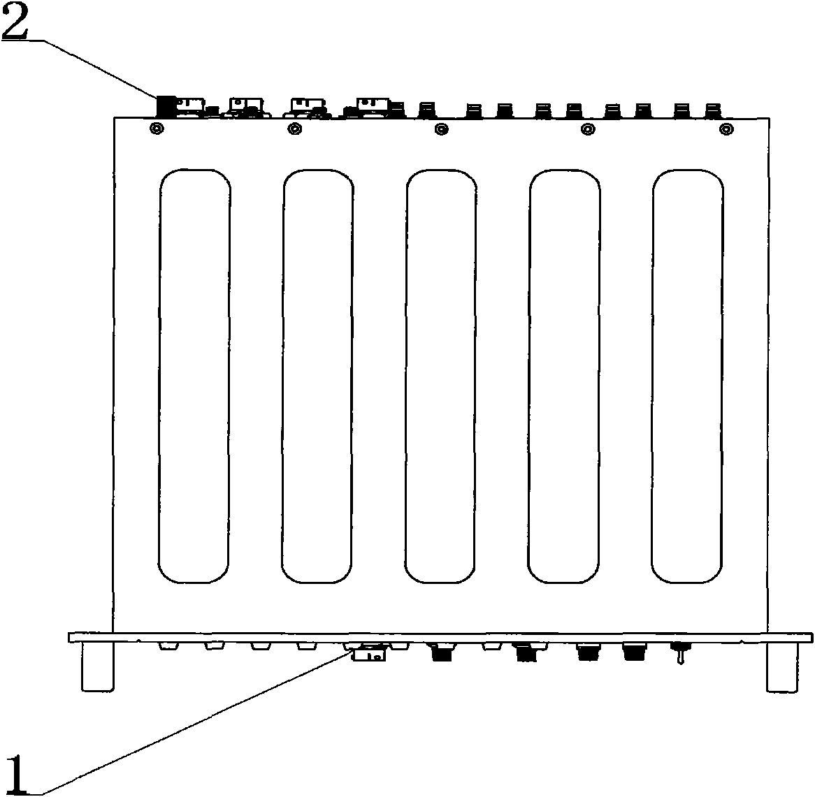
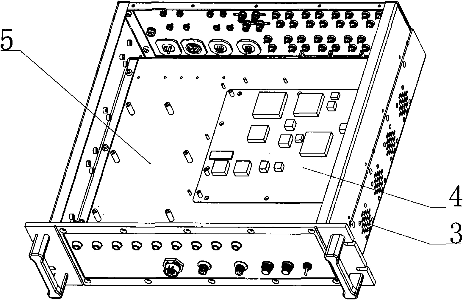
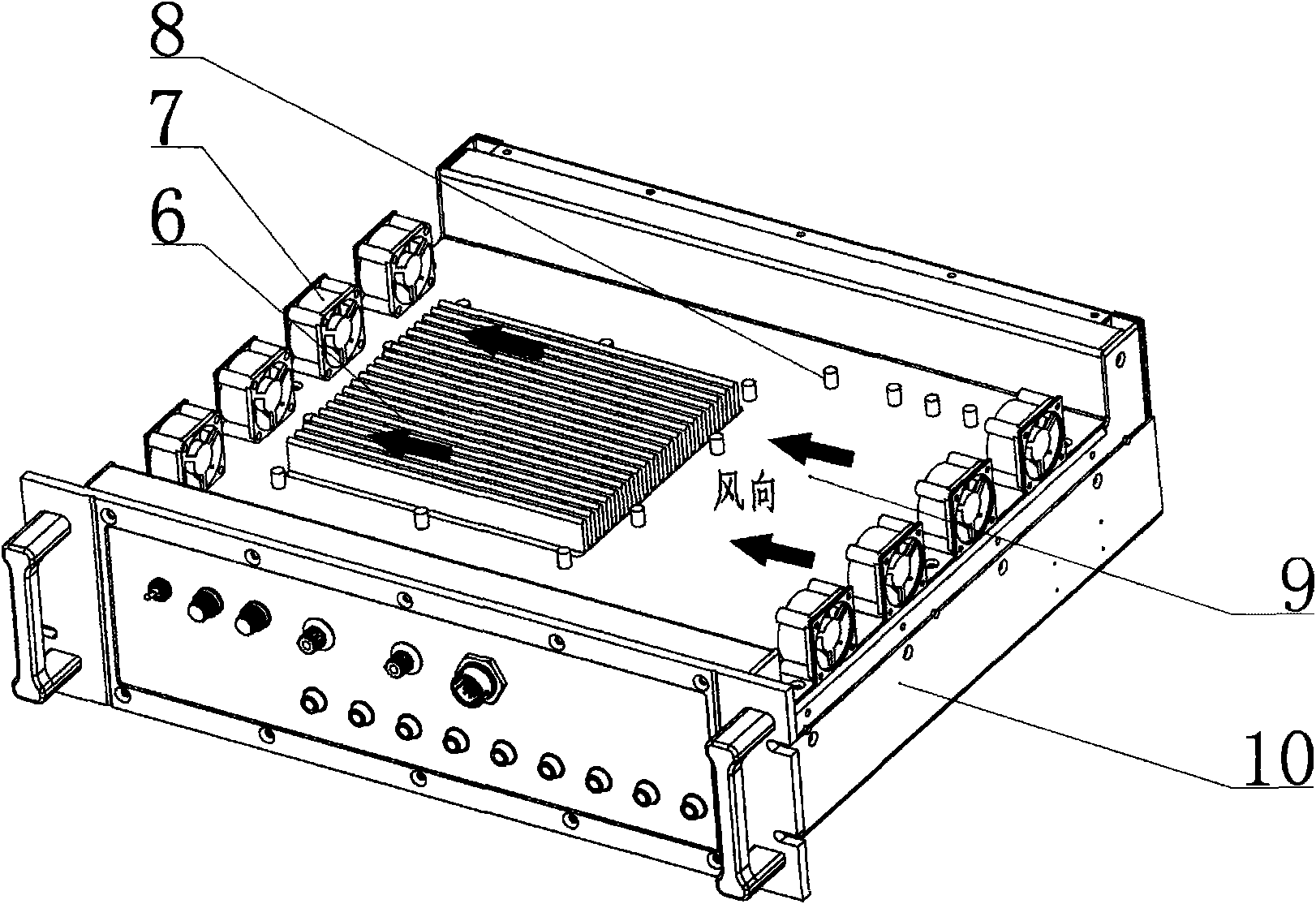
[0026] figure 1 It is a schematic diagram of the external structure of the electronic equipment chassis of the embodiment of the present invention, such as figure 1 As shown, the six surfaces of the external structure of the electronic equipment case are all made of metal materials, usually made of metals such as aluminum, copper, and iron with good thermal conductivity, or metal alloy materials such as copper alloys, aluminum alloys, and galvanized steel sheets. Wherein, the front panel 1 and the rear panel 2 of the chassis are provided with several through holes, the through holes are used to realize various interface functions, and corresponding device installation holes can be opened according to the functional requirements of the equipment. A part of the through holes is used to install c...


PUM


Abstract

The invention discloses an electronic equipment chassis and a radiating method thereof. By carrying out a splitting design to the installation of the electronic equipment chassis and a radiating part of a fan, the electronic equipment is arranged in a sealed area; a heat and good conductor material is adopted to tightly connect the sealed area and a radiating area in a back-to-back mode; the heat generated by the electronic equipment in the sealed area is taken away by the fan in the radiating area, thus reducing the temperature of the working area of the electronic equipment, namely, the sealed area, and realizing the purpose of radiating heat with high efficiency. The electronic equipment chassis can lead the electronic equipment to have the characteristics of dust prevention, rainproof performance and good electromagnetic compatibility.

Description

technical field [0001] The invention relates to an electronic equipment case, in particular to an electronic equipment case with good sealing, heat dissipation and electromagnetic compatibility and a heat dissipation method thereof. Background technique [0002] An electronic equipment case is usually an important device for protecting electronic circuit boards, shielding electromagnetic radiation, and supporting internal component structures. Since the circuit board onboard electronic components, semiconductor chips, and mechanical moving parts of the equipment will generate a lot of heat during the working process, if the heat generated cannot be taken away in time, the temperature inside the chassis will continue to rise, eventually causing The chip temperature of electronic equipment is too high, which will lead to unstable work, equipment failure, and even serious consequences such as chip burning and electronic equipment scrapping. Therefore, the problem of heat dissi...

Claims


Application Information

Patent Timeline
Patent Type & Authority Applications(China)
IPC IPC(8): H05K5/04H05K7/20H01L23/34H01L23/467G05D23/185G05D23/19
Inventor 张子兵
Owner SHANDONG INTELLIGENT OPTICAL COMM DEV
Learn More