
DC motor

A DC motor and magnetic yoke technology, applied in the field of DC motors, can solve problems such as generating electrical noise, and achieve the effects of increasing the duty cycle, realizing miniaturization, and reducing large-scale

Active Publication Date: 2009-11-18
MITSUBA CORP
View PDF2 Cites 3 Cited by
  • Summary
  • Abstract
  • Description
  • Claims
  • Application Information

AI Technical Summary

Problems solved by technology

[0006] In addition, when the segment is separated from the brush with the rotation of the armature, a discharge occurs between the brush and the segment by releasing the electromagnetic energy stored in the coil, whereby electrical noise may be generated

Method used


Image

  • DC motor
  • DC motor
  • DC motor

Examples


no. 1 approach

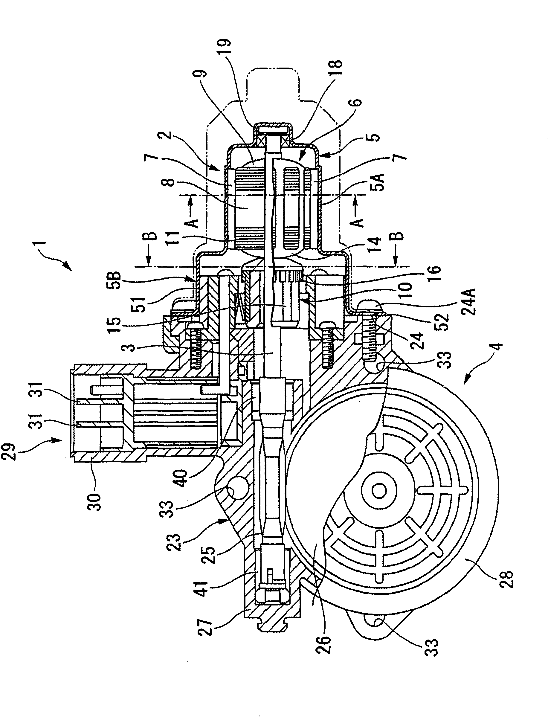
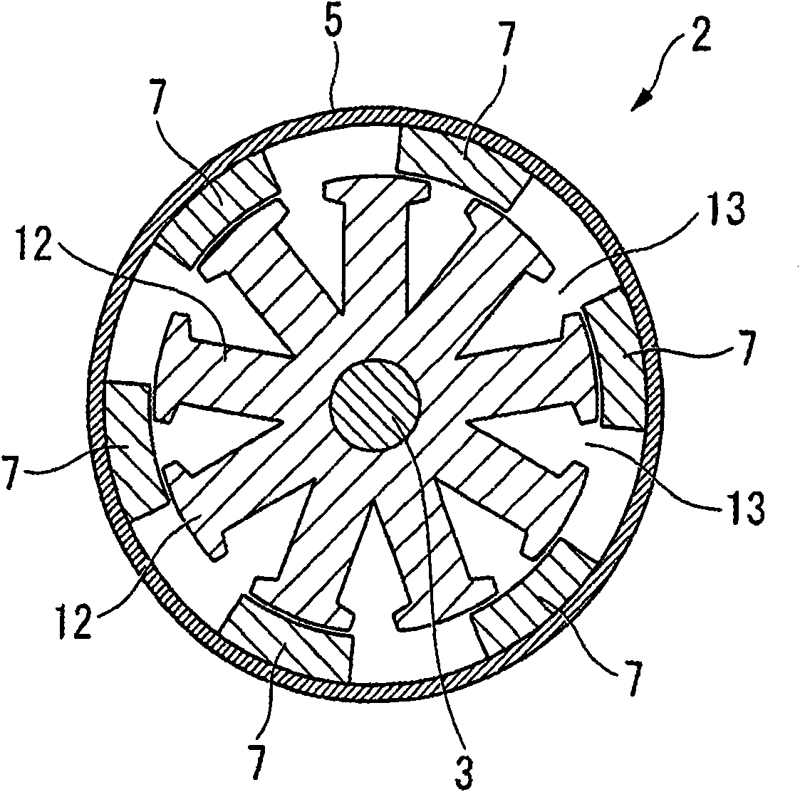
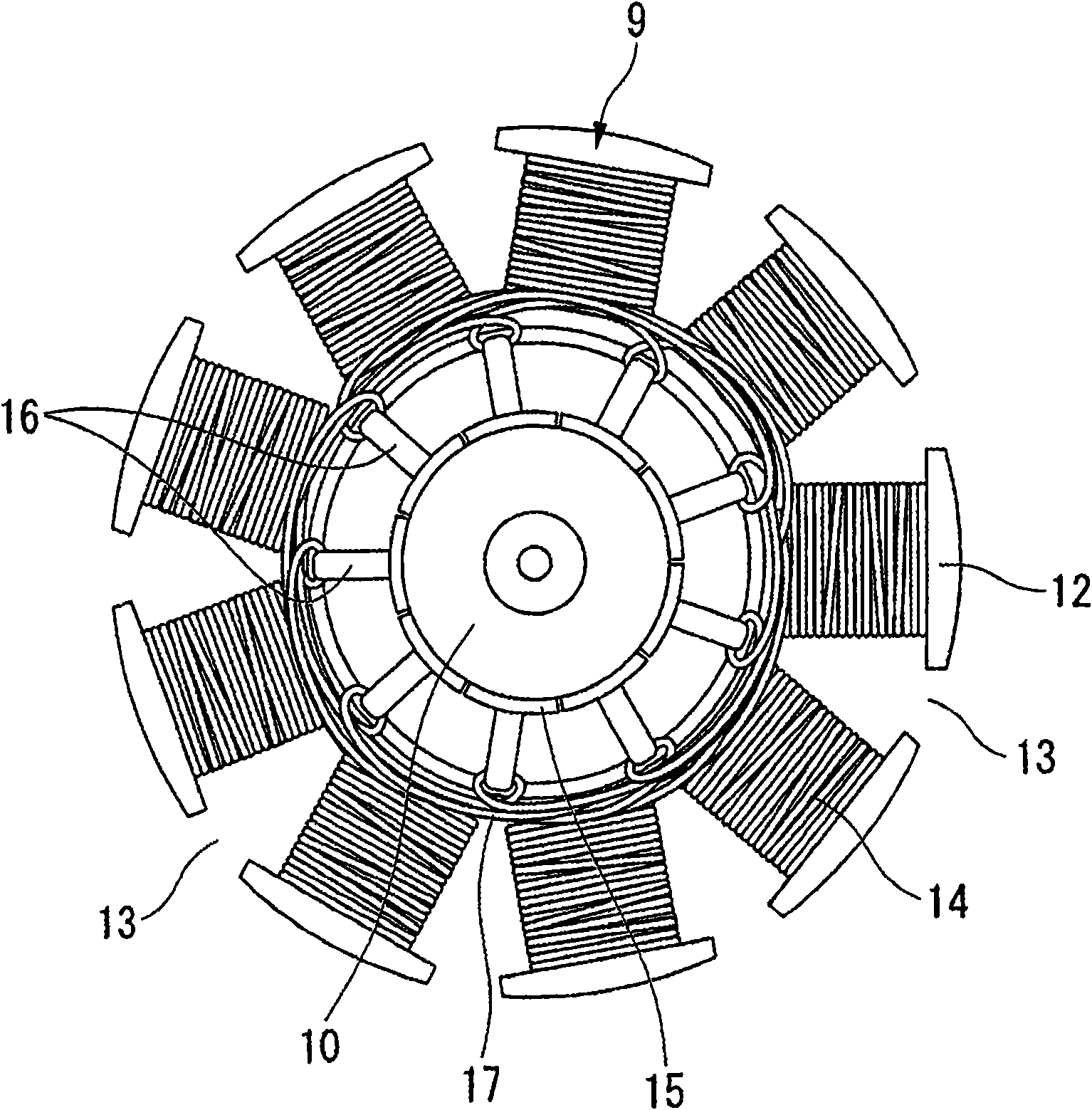
[0075] figure 1 It is a sectional view showing the structure of the automatic window device 1 for a vehicle using the DC motor 2 according to the present invention, figure 2 is along figure 1 A sectional view of the A-A line, image 3 is a top view of the armature 6, Figure 4 is along figure 1 B-B line sectional view.

[0076] Such as Figure 1 ~ Figure 4 As shown, the automatic window device 1 has a structure including a DC motor 2 and a worm gear reducer 4 connected to a rotating shaft 3 of the DC motor 2, and is incorporated in a door (not shown) of a vehicle. In addition, the two-dot chain line described around the DC motor 2 is a line showing the external shape of a conventional DC motor for comparison with the DC motor 2 of the present invention.

[0077] The DC motor 2 has a structure in which an armature 6 is rotatably arranged in a yoke case 5 having a bottomed cylindrical yoke main body 5A. Six shoe-shaped permanent magnets 7 divided in the circumferential d...


PUM


Abstract

An armature of a DC motor with a brush comprises a rotary shaft born by a yoke housing, an armature core fitted on the rotary shaft from outside and secured to the same, and a commutator provided to the rotary shaft adjacently to the armature core and having individual segments arranged circumferentially. The armature core has nine teeth radially extending and nine slots formed between teeth and axially extending. The segment at the same potential are interconnected through short-circuit members. A pair of brushes in slide contact with the segments is arranged point-symmetrically with respect to the rotary shaft. According to the invention, the DC motor flattening can be implemented.

Description

technical field [0001] The present invention relates to a DC motor mounted on a vehicle. This application claims priority based on Japanese Patent Application No. 2006-316141 filed in Japan on November 22, 2006 and Japanese Patent Application No. 2007-60355 filed in Japan on March 9, 2007, the contents of which are incorporated herein. Background technique [0002] Generally, DC motors with brushes are often used as electric motors mounted in vehicles such as automobiles. Such a DC motor has a structure in which two-pole or four-pole permanent magnets are arranged on the inner peripheral surface of a cylindrical yoke case, and an armature wound with an armature coil is rotatably arranged inside the permanent magnet. . As the permanent magnet, a sintered ferrite magnet formed into a tile shape is often used. The armature has an armature core fitted and fixed on the rotation shaft, and a plurality of axially long slots are formed in the armature core. [0003] A winding wi...

Claims


Application Information

Patent Timeline
Patent Type & Authority Applications(China)
IPC IPC(8): H02K23/38H02K23/04
CPCH02K13/10H02K5/148H02K7/1166H02K5/04H02K23/38H02K23/30
Inventor 盐田直树川岛义亲
Owner MITSUBA CORP
Learn More