Field weakening direction sensor calibration method

A technology of direction sensor and calibration method, applied in the direction of instrument, speed/acceleration/shock measurement equipment testing/calibration, measuring device, etc.

Inactive Publication Date: 2011-07-20
HEFEI INSTITUTES OF PHYSICAL SCIENCE - CHINESE ACAD OF SCI
View PDF5 Cites 0 Cited by
  • Summary
  • Abstract
  • Description
  • Claims
  • Application Information

AI Technical Summary

Problems solved by technology

However, this calibration method needs to measure 22 azimuth angle output values ​​of the field-weakening direction sensor, which is too complicated, and among the 22 positions, there are 45 degrees, 135 degrees, 225 degrees and 315 degrees in space. For the weak magnetic direction sensor whose shape is a rectangular parallelepiped block, it is easy to realize the spatial position at an integer multiple of 90 degrees, but it is more difficult to realize other positions, and the error is large, so this calibration method can achieve The accuracy can only be 3 to 5 degrees, and it is obviously not suitable for the weak magnetic direction sensor whose measurement accuracy has reached 0.5 degrees.
In addition, this calibration method is based on the assumption that the output characteristics of the field-weakening direction sensor are linear, so the output characteristics of the field-weakening direction sensor cannot be calibrated
[0005] The object of the present invention is to address the shortcomings of the large and expensive instruments required by the calibration method of the existing magnetic field weakening direction sensor, and propose a A method for calibration, which uses a one-dimensional rotating platform to calibrate the field-weakening direction sensor by using the output value changes of the field-weakening direction sensor in different spatial directions

Method used


Image

  • Field weakening direction sensor calibration method
  • Field weakening direction sensor calibration method
  • Field weakening direction sensor calibration method

Examples


Embodiment

[0058] The calibration of the three-dimensional electronic compass, the three-dimensional electronic compass uses the three-dimensional component of the geomagnetic field to determine the orientation of the object, and is widely used in navigation systems.

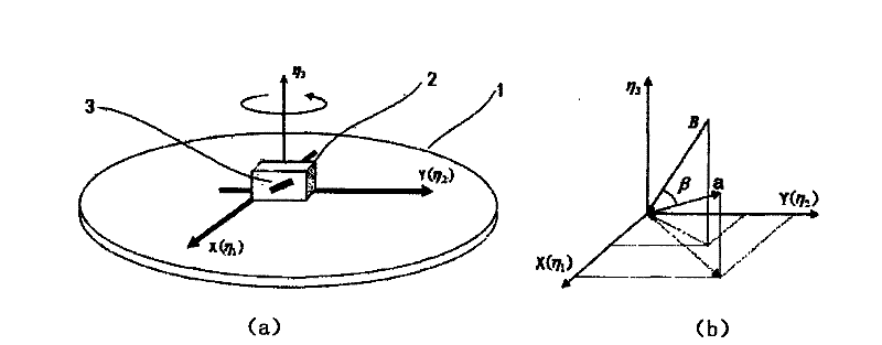
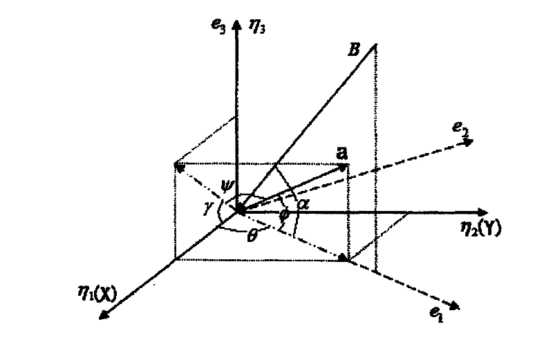
[0059] The calibration content is the direction angle and inclination angle of the electronic compass at any position and the external magnetic field. The shape of the electronic compass is a cuboid block, and the sensitive direction vectors of its three single-dimensional weak magnetic direction sensors are a, b, c, which are respectively related to the coordinate system η, (η 1 , η 2 , η 3 η in ) 1 , η 2 , η 3 form an acute angle; a, b, c form a three-dimensional space coordinate system (a, b, c); the three non-parallel edges of the electronic compass itself form a coordinate system η', (η' 1 , η' 2 , η' 3 ), which is horizontally related to the coordinate system η, (η 1 , η 2 , η 3 ) coincide; any orientation of...


PUM


Abstract

The invention discloses a field weakening direction sensor calibration method, especially a field weakening direction sensor calibration method used for the magnetic field response value equivalent toor less than that of the earth magnetic field. The realization apparatus of the method comprises a one-dimensional rotating platform with a horizontal table top, a cuboid block for containing the field weakening direction sensor; and the whole apparatus is nonmagnetic. The method comprises: determining the special position of the sensitive direction of the field weakening direction sensor in thecoordinate system composed by the magnetic field and the horizontal plane and the coordinate system of the cuboid block, by the sensor output variation along with the special position variation of thefield weakening direction sensor including 360-degrees rotation in horizontal direction on the one-dimensional rotating platform and the turning of integer times of the 90-degrees of the cuboid block; and determining the output characteristics of the field weakening direction sensor. The method need not magnetic shielding room or Helmholtz coil used in the conventional field weakening direction sensor calibration, can realize the high accuracy calibration to field weakening direction sensor by simple equipment.

Description

technical field [0001] The invention relates to the calibration of a magnetic field-weakening direction sensor, in particular to the calibration of a magnetic field-weakening direction sensor sensitive to direction by using the earth's magnetic field. Background technique [0002] Weak magnetic direction sensors are widely used in direction positioning and local detection due to their direction sensitivity, such as vehicle identification, earthquake monitoring, motion navigation, attitude display, etc. The field-weakening direction sensor will have different outputs when it is in different spatial angles, so its calibration content includes the output characteristics inside the field-weakening direction sensor and the spatial position relationship between the sensitive direction and the external structure of the sensor. [0003] The existing weak magnetic direction sensor calibration generally uses a non-magnetic method, which uses a magnetic shielding room or a three-dimen...

Claims


Application Information

Patent Timeline
Patent Type & Authority Patents(China)
IPC IPC(8): G01P21/00
Inventor 陈池来朱荣华林新华高理升
Owner HEFEI INSTITUTES OF PHYSICAL SCIENCE - CHINESE ACAD OF SCI
Why Eureka
Try Eureka