
A rotating electric component

A technology of electrical components and rotary type, which is applied in the direction of electrical components, circuits, electric switches, etc., and can solve problems such as damage operability, uneven torque, thermal deformation of rotating parts, etc.

Active Publication Date: 2011-09-28
ALPS ALPINE CO LTD
View PDF1 Cites 0 Cited by
  • Summary
  • Abstract
  • Description
  • Claims
  • Application Information

AI Technical Summary

Problems solved by technology

[0004] However, in the conventional rotary electric components as described above, if they are exposed to high temperature in a reflow soldering process, etc., local thermal deformation of the rotary component due to the biasing force of the leaf spring may occur.
In this case, there is a problem that unevenness occurs in the torque due to the difference in the rotational position of the rotating shaft, and operability is impaired.

Method used


Image

  • A rotating electric component
  • A rotating electric component
  • A rotating electric component

Examples


Embodiment Construction

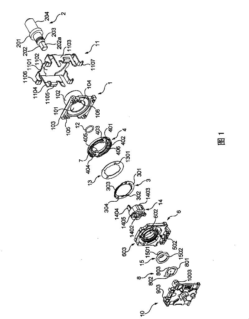
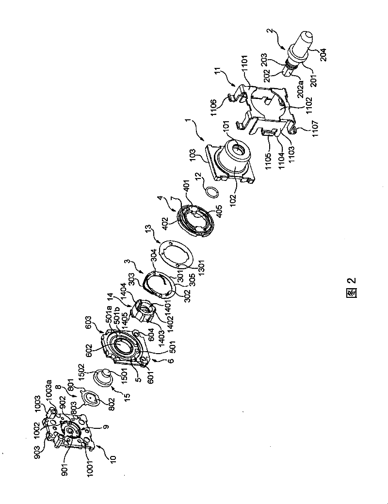
[0025] Hereinafter, embodiments of the present invention will be described in detail with reference to the drawings. figure 1 as well as figure 2 It is an exploded perspective view of a rotary electric component according to an embodiment of the present invention. figure 1 as well as figure 2 It is an exploded perspective view of a rotary electric component shown from different directions. Also, in the following, for convenience, the figure 1 The left side shown is called "the rear side of the rotary electrical component" or simply "the rear side", and the right side shown in the figure is called the "front side of the rotary electrical component" or simply "the front side". side".

[0026] Such as figure 1 as well as figure 2 As shown, the rotary electric component of this embodiment generally includes a metal bearing member 1 having a through hole 101, a rotating shaft 2 as a shaft member rotatably inserted through the through hole 101 of the bearing member 1, and a...


PUM


Abstract

The invention provides a rotating electric component that prevents disproportion of a torquemoment with favorable operability, wherein the rotating electric component characterized in that the invention comprises the following components: a bearing component (1) provided with a through hole (101) that made of metal; a rotational axis (2) that can insert into the through hole (101) rotatablely; a sliding part bearing part (4) that can hold a sliding part (3) and rotates with the rotational axis (2); an insulation component (6) provided with conductive pattern (501) that connected with the sliding part (3) in a sliding way; a plate spring (7) that exerts load to rotation of the rotational axis (2). In the rotating electric component, the plate spring (7) is mounted on the sliding part bearing part (4) and a spring connection part locally set on the plate spring (7) connects with interior surface of the sliding part bearing part (4).

Description

technical field [0001] The present invention relates to a rotary electric component, and particularly to a rotary electric component used for various controls of electronic equipment and the like. Background technique [0002] Conventionally, there is known a rotary electric component that obtains the torque of the rotary shaft by pressing a leaf spring against the rotary member that rotates together with the rotary shaft for the rotary operation (for example, refer to Patent Document 1). In this rotary electric component, a leaf spring made of a metal material is pressed against a rotating member made of synthetic resin, thereby obtaining a torque of the rotating shaft. [0003] [Patent Document 1] Japanese Patent Laid-Open No. 2006-260826 [0004] However, in the conventional rotary electric component as described above, when exposed to high temperature in a reflow soldering process or the like, local thermal deformation of the rotary component to which the biasing force ...

Claims


Application Information

Patent Timeline
Patent Type & Authority Patents(China)
IPC IPC(8): H01C10/32H01H19/02H01F29/06H01G5/01
Inventor 沟渊慎一横山公宏
Owner ALPS ALPINE CO LTD
Learn More