Heat generating body unit and heating apparatus

A heating element unit and heating device technology, applied in the direction of ohmic resistance heating device, electric heating device, heating element, etc., can solve the problems of uneven temperature, cracks, non-flexibility, etc., and achieve the effect of easy design and small efficiency

Inactive Publication Date: 2009-11-25
PANASONIC CORP
View PDF1 Cites 7 Cited by
  • Summary
  • Abstract
  • Description
  • Claims
  • Application Information

AI Technical Summary

Problems solved by technology

In the conventional heating element formed in this way, in the state where the carbon fibers are connected, the thermal conductivity in the direction parallel to the carbon fibers (carbon fiber direction) is excellent, but when processing is performed for the purpose of resistance adjustment, etc., the carbon fibers are partially cut , therefore, the thermal conductivity in the carbon fiber direction deteriorates sharply
In addition, since the thermal conductivity in the direction perpendicular to the carbon fiber direction is low, temperature unevenness occurs in each heat generating element unit as a heat source, and there is a problem in terms of reliability.
Furthermore, the cut portion of the carbon fiber becomes the starting point, and cracks occur, resulting in a problem that the life is shortened
[0007] In addition, the heating element in the conventional heating element unit has a structure in which carbon fibers are fixed with resin, so it is not flexible, and it is difficult to meet various specifications required as a heat source in a heating device.

Method used


Image

  • Heat generating body unit and heating apparatus
  • Heat generating body unit and heating apparatus
  • Heat generating body unit and heating apparatus

Examples


Embodiment approach 1

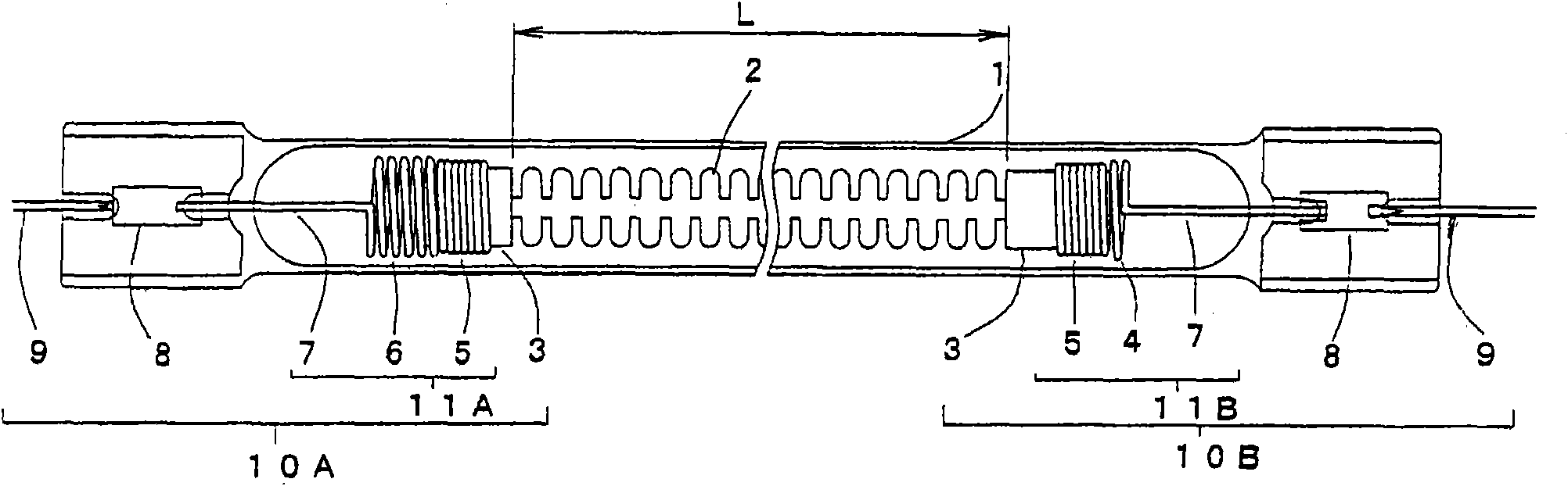
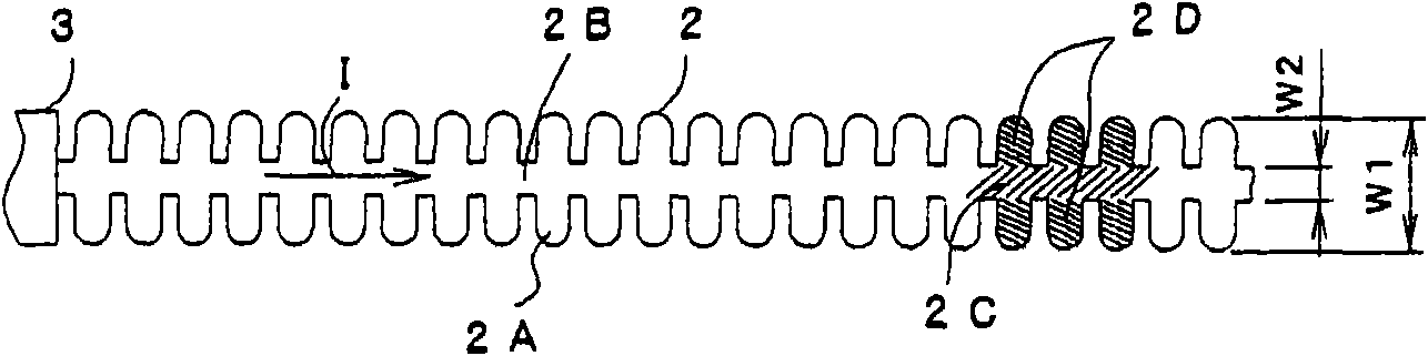
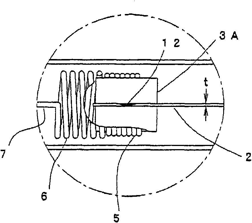
[0052] use Figure 1 ~ Figure 3 , the heat generating unit according to Embodiment 1 of the present invention will be described. figure 1 It is a front view showing the structure of the heat generating unit of Embodiment 1. exist figure 1 In , since the heat generating unit has a long strip shape, its middle part is cut off and omitted, and the vicinity of both end parts is shown. figure 2 It is a front view showing a part of the heat generating body in the heat generating body unit according to the first embodiment. image 3 It is an enlarged view showing a part of the heat generating unit according to Embodiment 1 enlargedly.

[0053] In the heating element unit according to Embodiment 1, the elongated heating element 2 is arranged inside a glass tube 1 made of transparent quartz glass, and the heating element 2 extends along the longitudinal direction of the glass tube 1 . In addition, both ends of the glass tube 1 are welded in a flat shape, and the heating element 2 ...

Embodiment approach 2

[0107] Below, use Figure 5 , and the heat generating unit according to Embodiment 2 of the present invention will be described. Figure 5 It is a front view showing specific examples of various shapes of the heat generating element in the heat generating element unit according to the second embodiment. exist Figure 5 Among the heating elements in , the heating element is long and repeats the same pattern shape, so the right part is omitted.

[0108] The heat generating unit of Embodiment 2 differs from the heat generating unit of Embodiment 1 in the shape of the heat generating body, and is the same as Embodiment 1 in other respects. Therefore, the shape of the heat generating element in the heat generating element unit according to Embodiment 2 will be described, and the description of Embodiment 1 will apply to other components.

[0109] The heat generating element in the heat generating element unit according to Embodiment 2 does not make the temperature distribution u...

Embodiment approach 3

[0119] Below, use Image 6 , and the heat generating unit according to Embodiment 3 of the present invention will be described. Image 6 It is a front view showing specific examples of various shapes of the heat generating element in the heat generating element unit according to the third embodiment. exist Image 6 In , each heating element is in the shape of a strip, which is a repetition of the same pattern shape, so the right part is omitted.

[0120] The heat generating unit of Embodiment 3 differs from the heat generating unit of Embodiment 1 in the shape of the heat generating body, and is the same as Embodiment 1 in other respects. Therefore, the shape of the heat generating element in the heat generating element unit according to Embodiment 3 will be described, and the description of Embodiment 1 will apply to other structural requirements.

[0121] The heat generating element in the heat generating element unit according to Embodiment 3 does not make the temperatur...


PUM


Abstract

Provided are a heat generating body unit, which is small, has high efficiency and directivity, performs uniform heating and starts quickly, and a heating apparatus using such heat generating body unit. A heat generating body (2) in the heat generating body unit is formed of a material having a carbonaceous material as a main component in a film sheet shape, and the heat generating body has equivalent heat conductivity in the planar direction. When power supplying sections (10A, l0B) supply power to facing both ends of the heat generating body (2), the heat generating body (2) in the heat generating body unit generates heat on the entire surface at a high efficiency.

Description

technical field [0001] The present invention relates to a heating element unit used as a heat source and a heating device using the heating element unit, in particular to a heating element unit having a heating element formed in a thin film sheet mainly composed of a carbonaceous material and a heating element using the heating element unit. Heating device for heating element unit. Background technique [0002] A conventional heating element unit used as a long heat source is configured by enclosing a coil-shaped tungsten wire or a rod-shaped or plate-shaped carbon-based sintered body as a heating element inside a cylindrical glass tube. Examples of heating devices using such heat generating units include electronic devices such as copiers, facsimile machines, and printers, and various devices that require a heat source, such as electric heating devices, cooking devices, and dryers. [0003] As described above, in various devices, heat generating units are widely used as he...

Claims


Application Information

Patent Timeline
Patent Type & Authority Applications(China)
IPC IPC(8): H05B3/44H05B3/00H05B3/06H05B3/14
CPCH05B2203/032H05B3/009H05B3/44H05B3/0033H05B3/00H05B3/06H05B3/14
Inventor 小西政则冈原嗣典松冈广彰西尾章
Owner PANASONIC CORP
Why Eureka
Try Eureka