Lens drive device

A lens drive device and lens technology, applied in the field of photography, can solve the problems of low magnetic field utilization rate and weak magnetic field, and achieve the effects of increased magnetic field utilization rate, reduced magnetic flux leakage, and improved EMI

Inactive Publication Date: 2013-06-19
JOHNSON ELECTRIC SHENZHEN
View PDF0 Cites 0 Cited by
  • Summary
  • Abstract
  • Description
  • Claims
  • Application Information

AI Technical Summary

Problems solved by technology

[0004] The direction of the magnetic flux of the magnet 12 is as follows figure 1 As shown in the direction of the middle arrow, since the lens holder 114 is a moving part, the inner ring 112 of the iron shell must be shorter than the length of the outer ring 111 and the magnet 12, and a large part of the magnetic flux generated by the magnet 12 cannot enter the inner ring 112. However, this part of the magnetic flux that fails to enter the inner ring 112 encounters a relatively large magnetic resistance, so the magnetic field corresponding to the coil part is relatively weak, and the utilization rate of the magnetic field is low.

Method used


Image

  • Lens drive device
  • Lens drive device
  • Lens drive device

Examples


Embodiment Construction

[0016] In order to make the technical problems to be solved, technical solutions and beneficial effects of the present invention clearer, the present invention will be further described in detail below in conjunction with the accompanying drawings and embodiments. It should be understood that the specific embodiments described here are only used to explain the present invention, not to limit the present invention.

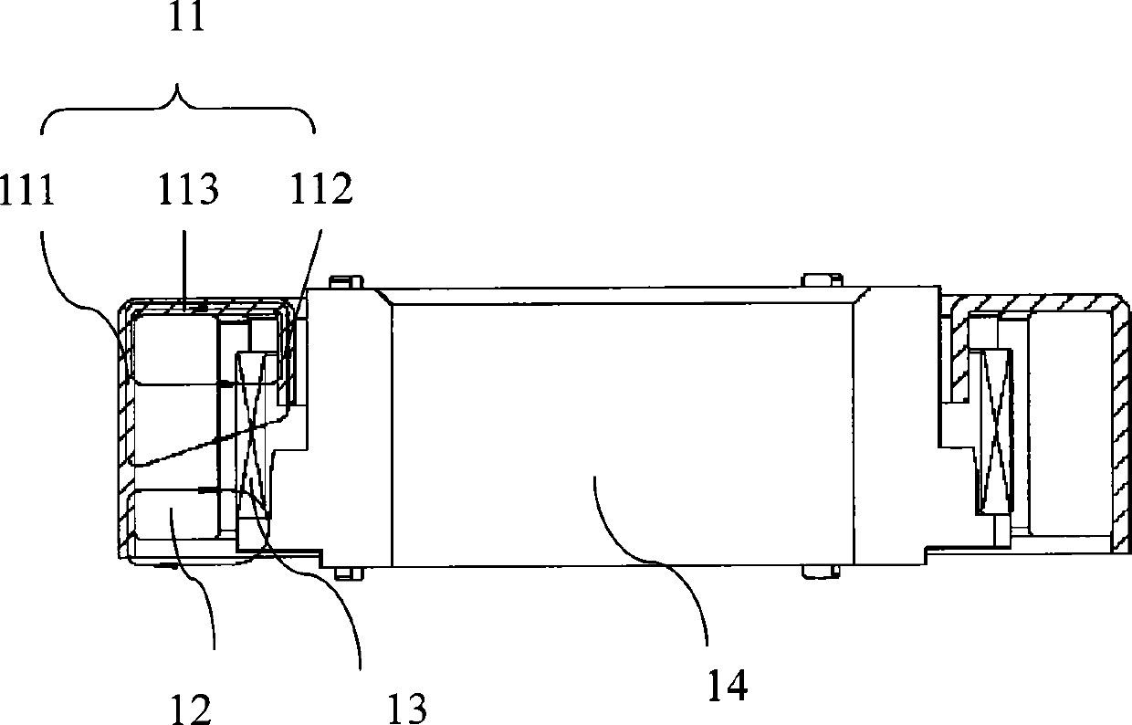
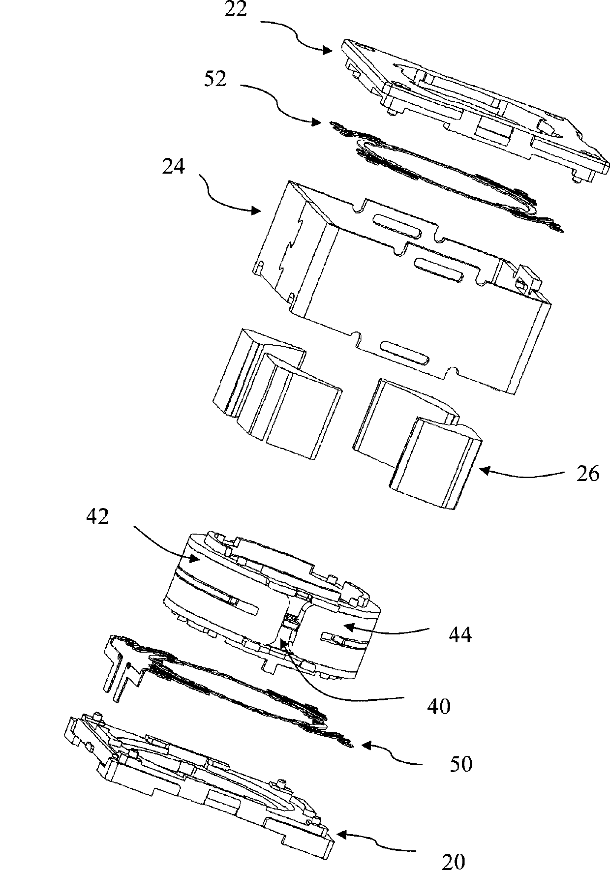
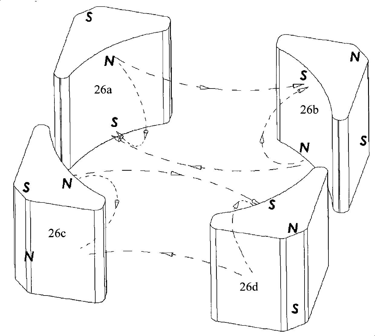
[0017] A lens driving device provided by an embodiment of the present invention includes a stationary part, a moving part, and a driving part for driving the moving part to move relative to the stationary part along the optical axis of the lens. The driving part includes a plurality of magnets fixed on one of the stationary part and the moving part, and at least two coils fixed on the other of the stationary part and the moving part, facing the magnet. For the convenience of description, the magnets in the following embodiments are fixed to the stationary part, whi...


PUM


Abstract

The invention provides a lens drive device which comprises a fixed part, a movable part and a drive part for driving the movable part to move relative to the fixed part. The drive part comprises a plurality of magnets, wherein the magnets are fixed on the fixed part or the movable part, arranged along the circumferential direction of a lens and polarized along the radial direction of the lens; each magnet is divided into a plurality of layers along the axial direction of the lens, and the polarization directions of every two adjacent layers are opposite, thereby leading the magnets to form a magnetic loop in an axial plane of the parallel lenses; and the polarization directions of the corresponding layers of at least two adjacent magnets are opposite, thereby leading the two adjacent magnets to form the magnetic loop together. The drive part also comprises at least two coils fixed in the fixed part or the movable part, wherein each coil comprises the two adjacent layers respectively towards the corresponding magnets along the axial direction of the lens. Each coil is simultaneously positioned in a plurality of magnetic loops, thereby greatly reinforcing the intensity of a magneticfield in which the coils are positioned, reducing magnetic flux leakage, improving EMI and increasing the utilization ratio of the magnetic field.

Description

technical field [0001] The invention belongs to the technical field of imaging, and in particular relates to a lens driving device. Background technique [0002] Video electronic products such as digital cameras, digital video cameras, mobile phones with camera functions, and notebook computers with cameras are usually equipped with lenses. A commonly used lens driving method in the prior art is to drive through a coil and a magnet to generate electromagnetic force. The lens moves on the optical axis. [0003] figure 1 Shown is a lens driving device in the prior art, which includes an iron shell 11, a magnet 12, a coil 13 and a lens frame 14, the magnet 12 and the iron shell 11 are fixed as a stationary part, and the coil 13 is fixedly sleeved on the lens frame 14 The lateral fixation serves as the moving part, which can move relative to the stationary part. The iron shell 11 includes an outer ring 111, an inner ring 112 and a yoke 113, the outer ring 111 and the inner ri...

Claims


Application Information

Patent Timeline
Patent Type & Authority Patents(China)
IPC IPC(8): G02B7/04H02K33/18
Inventor 李越
Owner JOHNSON ELECTRIC SHENZHEN
Why Eureka
Try Eureka