Power supply method and power supply system by using optical network element
A power supply method and optical network technology, applied in the field of optical network elements, can solve problems affecting optical network element services, power supply interruptions, etc., and achieve good operation and control, increased stability, and fast data processing effects
- Summary
- Abstract
- Description
- Claims
- Application Information
AI Technical Summary
Problems solved by technology
Method used
Image
Examples
Embodiment 1
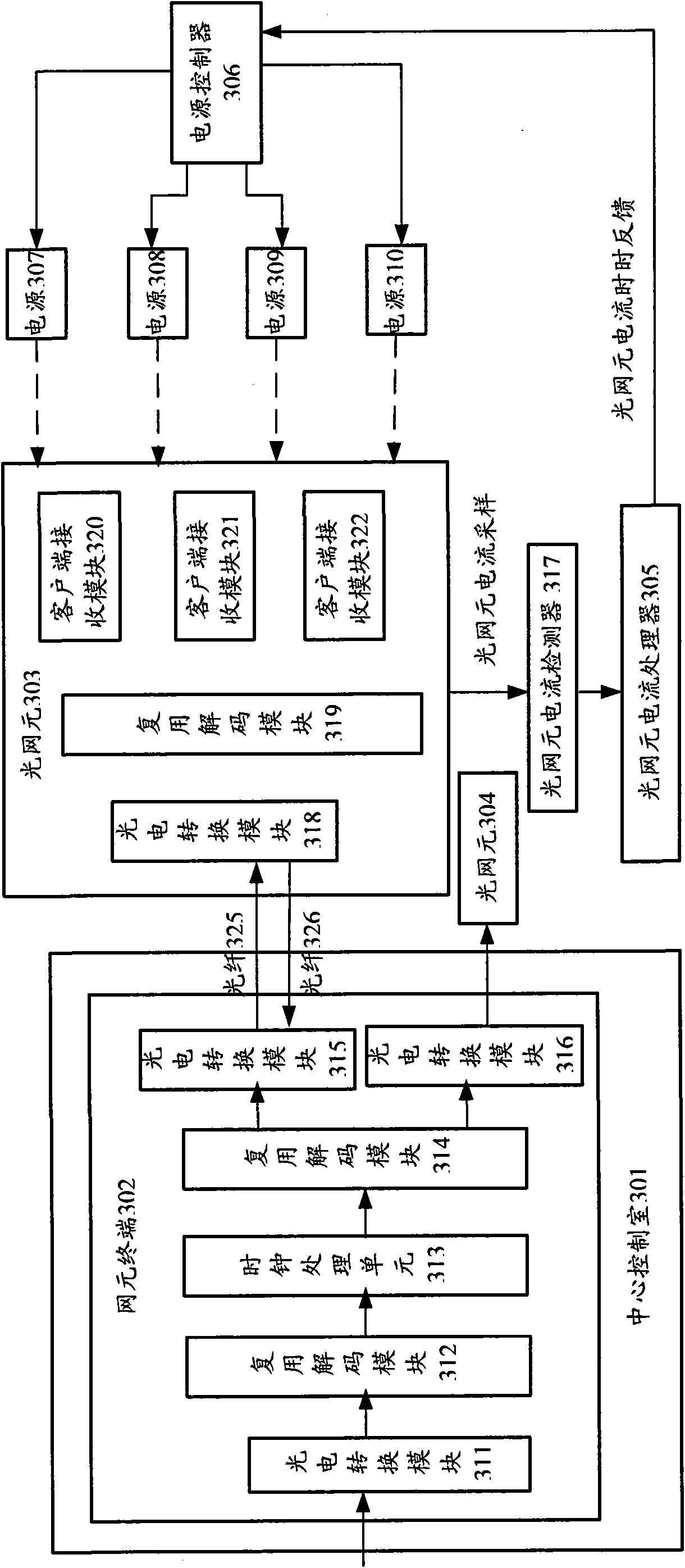
[0042] This example is a system that supplies power to a single optical network element, such as image 3 As shown, the power supply system supplies power to the optical network element 303 , including a power supply 307 , a power supply 308 , a power supply 309 , and a power supply 310 , as well as an optical network element current detector 317 , an optical network element current processor 305 and a power supply controller 306 .
[0043] The central control room 301 controls the network element terminal 302 to communicate with the optical network element 303 through the optical fiber 325. The photoelectric conversion module 318 of the optical network element 303 converts the optical signal transmitted by the optical fiber into an electrical signal. At the same time, the optical network element 303 receives the Modules 320, 321 and 322 are connected to clients (not shown). In practical applications, there may be multiple client receiving modules. The electrical signals rece...
Embodiment 2
[0046] In this example, the system that supplies power to two optical network elements is as follows: Figure 4 As shown, it includes power supplies 428, 429, 430, and 431, as well as an optical network element current detector 425, an optical network element current processor 427, and a power supply controller.
[0047] In this example, the optical network element 413 is powered by the power supplies 428 and 429 at the same time to work normally. The current data is sent to the optical network element current processor 427 through the optical network element current sampling, and the optical network element current processor 427 processes the sampled data. When a large enough current cannot be provided for the optical network element 419 to work, the optical network element current processor 427 feeds back the optical network element current and notifies the power controller 433 to turn on the power supply 430 to supply power to the optical network element 419; if the optical n...
Embodiment 3
[0049] This example is a system that supplies power to multiple optical network elements, such as Figure 5 As shown, it includes power supplies 537 , 538 , 539 , and 540 , as well as an optical network element current detector 535 , an optical network element current processor 536 , and a power supply controller 541 .
[0050] In this example, the optical network elements 531 and 532 are in the working state. In the central control room 510, the optical network elements 531 and 532 communicate with the optical network elements 531 and 532 via optical fibers 543 and 544 through the photoelectric conversion modules 506 and 507 of the network element terminal 501, respectively. The working current of the optical network elements 531 and 532 is provided by the power supply 537 . At a certain moment, due to business needs, the optical network element 533 starts to work, and the current of the optical network elements 531, 532, and 533 is detected by the optical network element cur...
PUM
 Abstract
Description
Claims
Application Information
 - R&D
- Intellectual Property
- Life Sciences
- Materials
- Tech Scout
- Unparalleled Data Quality
- Higher Quality Content
- 60% Fewer Hallucinations
Browse by: Latest US Patents, China's latest patents, Technical Efficacy Thesaurus, Application Domain, Technology Topic, Popular Technical Reports.
© 2025 PatSnap. All rights reserved.Legal|Privacy policy|Modern Slavery Act Transparency Statement|Sitemap|About US| Contact US: help@patsnap.com


