Power supply method and power supply system by using optical network element

A power supply method and optical network technology, applied in the field of optical network elements, can solve problems affecting optical network element services, power supply interruption, etc., and achieve the effects of good operation and control, increased stability, and fast data processing.

Inactive Publication Date: 2012-05-23
ZTE CORP
View PDF0 Cites 0 Cited by
  • Summary
  • Abstract
  • Description
  • Claims
  • Application Information

AI Technical Summary

Problems solved by technology

[0006] In the existing technology, the independent power supply mode of optical network elements, each optical network element has an independent power supply, but when the power supply fails or overcurrent, the power supply will still be interrupted, thus affecting the business of the optical network element

Method used


Image

  • Power supply method and power supply system by using optical network element
  • Power supply method and power supply system by using optical network element
  • Power supply method and power supply system by using optical network element

Examples


Embodiment 1

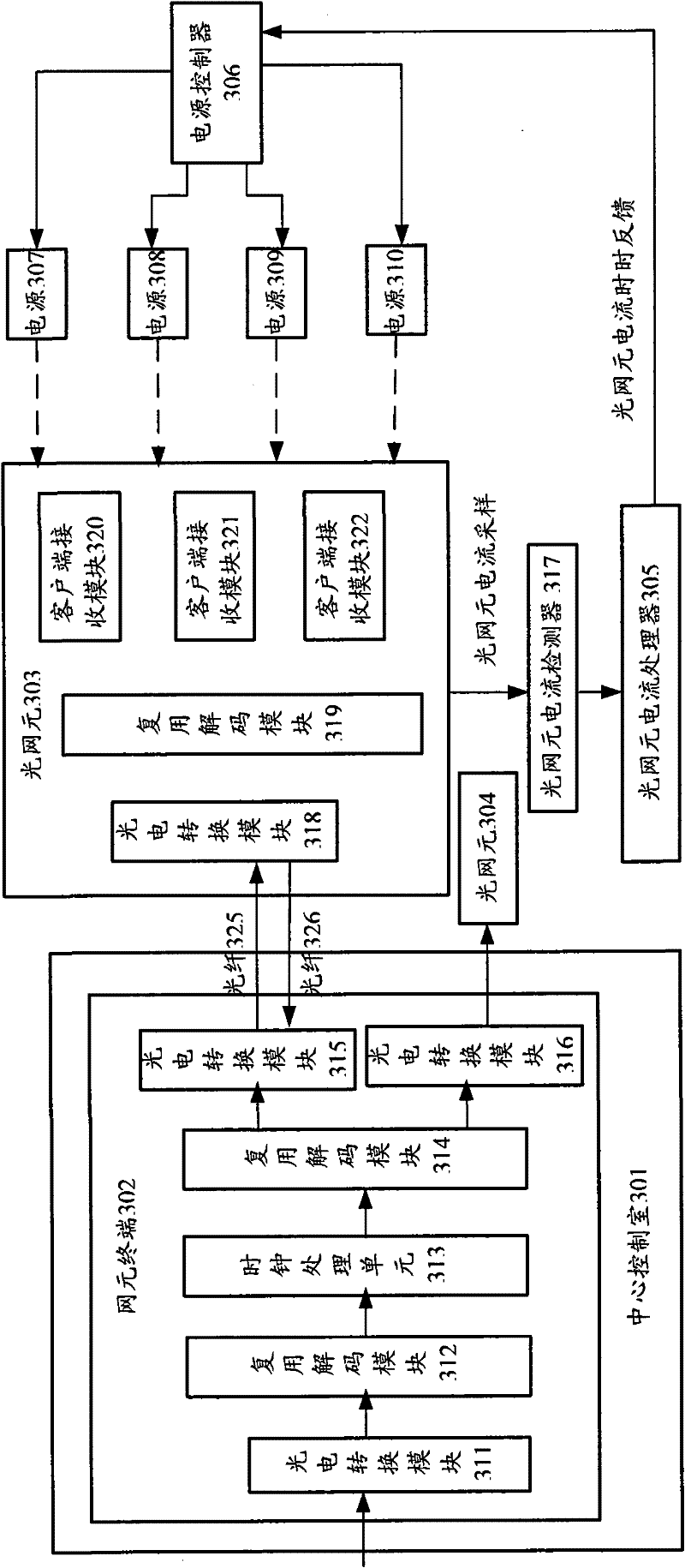
[0042] This example is a system that supplies power to a single optical network element, such as image 3 As shown, the power supply system supplies power to the optical network element 303 , including a power supply 307 , a power supply 308 , a power supply 309 , and a power supply 310 , as well as an optical network element current detector 317 , an optical network element current processor 305 and a power supply controller 306 .

[0043] The central control room 301 controls the network element terminal 302 to communicate with the optical network element 303 through the optical fiber 325. The photoelectric conversion module 318 of the optical network element 303 converts the optical signal transmitted by the optical fiber into an electrical signal. At the same time, the optical network element 303 receives the Modules 320, 321 and 322 are connected to clients (not shown). In practical applications, there may be multiple client receiving modules. The electrical signals rece...

Embodiment 2

[0046] In this example, the system that supplies power to two optical network elements is as follows: Figure 4 As shown, it includes power supplies 428, 429, 430, and 431, as well as an optical network element current detector 425, an optical network element current processor 427, and a power supply controller.

[0047] In this example, the optical network element 413 is powered by the power supplies 428 and 429 at the same time to work normally. The current data is sent to the optical network element current processor 427 through the optical network element current sampling, and the optical network element current processor 427 processes the sampled data. When a large enough current cannot be provided for the optical network element 419 to work, the optical network element current processor 427 feeds back the optical network element current and notifies the power controller 433 to turn on the power supply 430 to supply power to the optical network element 419; if the optical n...

Embodiment 3

[0049] This example is a system that supplies power to multiple optical network elements, such as Figure 5 As shown, it includes power supplies 537 , 538 , 539 , and 540 , as well as an optical network element current detector 535 , an optical network element current processor 536 , and a power supply controller 541 .

[0050] In this example, the optical network elements 531 and 532 are in the working state. In the central control room 510, the optical network elements 531 and 532 communicate with the optical network elements 531 and 532 via optical fibers 543 and 544 through the photoelectric conversion modules 506 and 507 of the network element terminal 501, respectively. The working current of the optical network elements 531 and 532 is provided by the power supply 537 . At a certain moment, due to business needs, the optical network element 533 starts to work, and the current of the optical network elements 531, 532, and 533 is detected by the optical network element cur...


PUM


Abstract

The invention discloses a power supply method by using an optical network element, which comprises a process of carrying out selectional starting on at least two power supplies connected to the optical network element. The process comprises the following steps: sampling power supply current of the optical network element; determining a starting proposal of the power supplies connected to the optical network element based on the sampling result; and supplying power to the optical network element by the power supplies according to the starting proposal. The invention also discloses a power supply system by using the optical network element. The method and the system determine the starting proposal of a plurality of the power supplies connected to the optical network element by sampling the current of the optical network element, so that when certain power supply is faulty or generates overcurrent, other power supplies are used or added for supplying the power to realize crossfeed and mutual backup among the power supplies and improve the stability of the system.

Description

technical field [0001] The present invention relates to the field of optical network elements, in particular to a method and system for simultaneously supplying power to a single or multiple optical network elements. Background technique [0002] At present, the power supply mode of ONU (Optical Network Unit: Optical Network Unit) is based on the recommendation of ITU-TL.44, using one of the following three methods for power supply, namely: central control room power supply, local power supply and optical network element Independent power supply. [0003] The power supply of the central control room needs to be provided by a central control room to supply power to each optical network element. In this case, the equipment supplier is required to manage the power supply of the optical network element, and whether the power supply line of the power supply is routed separately or together with the optical fiber Lines will increase the cost of equipment suppliers, so it is not s...

Claims


Application Information

Patent Timeline
Patent Type & Authority Patents(China)
IPC IPC(8): H02J9/06G05B19/04
CPCH04Q2011/0081H04Q11/0067H04B10/808
Inventor 侯明鑫
Owner ZTE CORP
Why Eureka
Try Eureka