Clutch device of output shaft of gear-box for lawn-mower

A clutch device and output shaft technology, which is applied to mechanical drive clutches, clutches, harvesters, etc., can solve the problems of unsuitable structures with small radial dimensions and large radial dimensions of clamping rings, and achieve compact structure and improved performance. Reliable, high hardness effect

Inactive Publication Date: 2009-12-09
JIANGSU WORLD PLANT PROTECTING MACHINERY
View PDF1 Cites 9 Cited by
  • Summary
  • Abstract
  • Description
  • Claims
  • Application Information

AI Technical Summary

Problems solved by technology

However, the radial size of the clamping ring of this invention is relatively large, so it is not suitable for structures with small radial dimensions; in addition, the combination or separation of the clutch mechanism is realized by rotating the clamping ring, which cannot be used for some The device that rotates to realize the coupling or disengagement of the clutch mechanism cannot be used

Method used


Image

  • Clutch device of output shaft of gear-box for lawn-mower
  • Clutch device of output shaft of gear-box for lawn-mower
  • Clutch device of output shaft of gear-box for lawn-mower

Examples


Embodiment Construction

[0020] The present invention will be further described below in conjunction with drawings and embodiments.

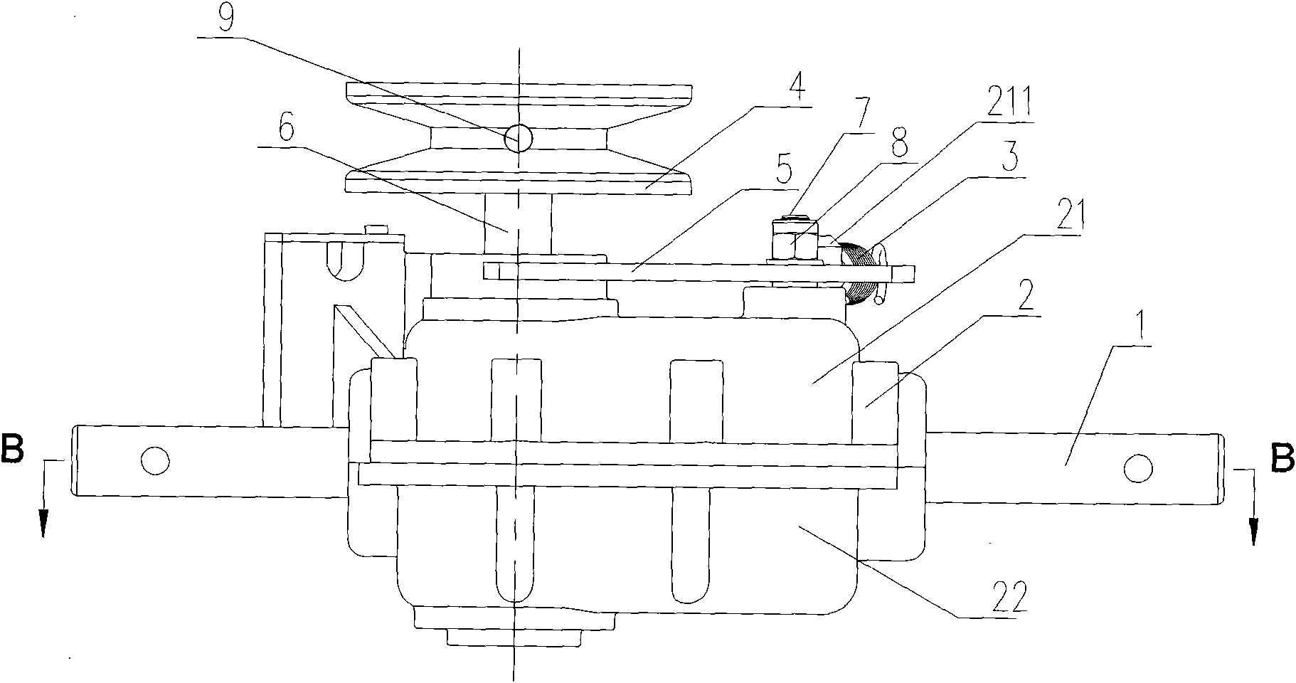
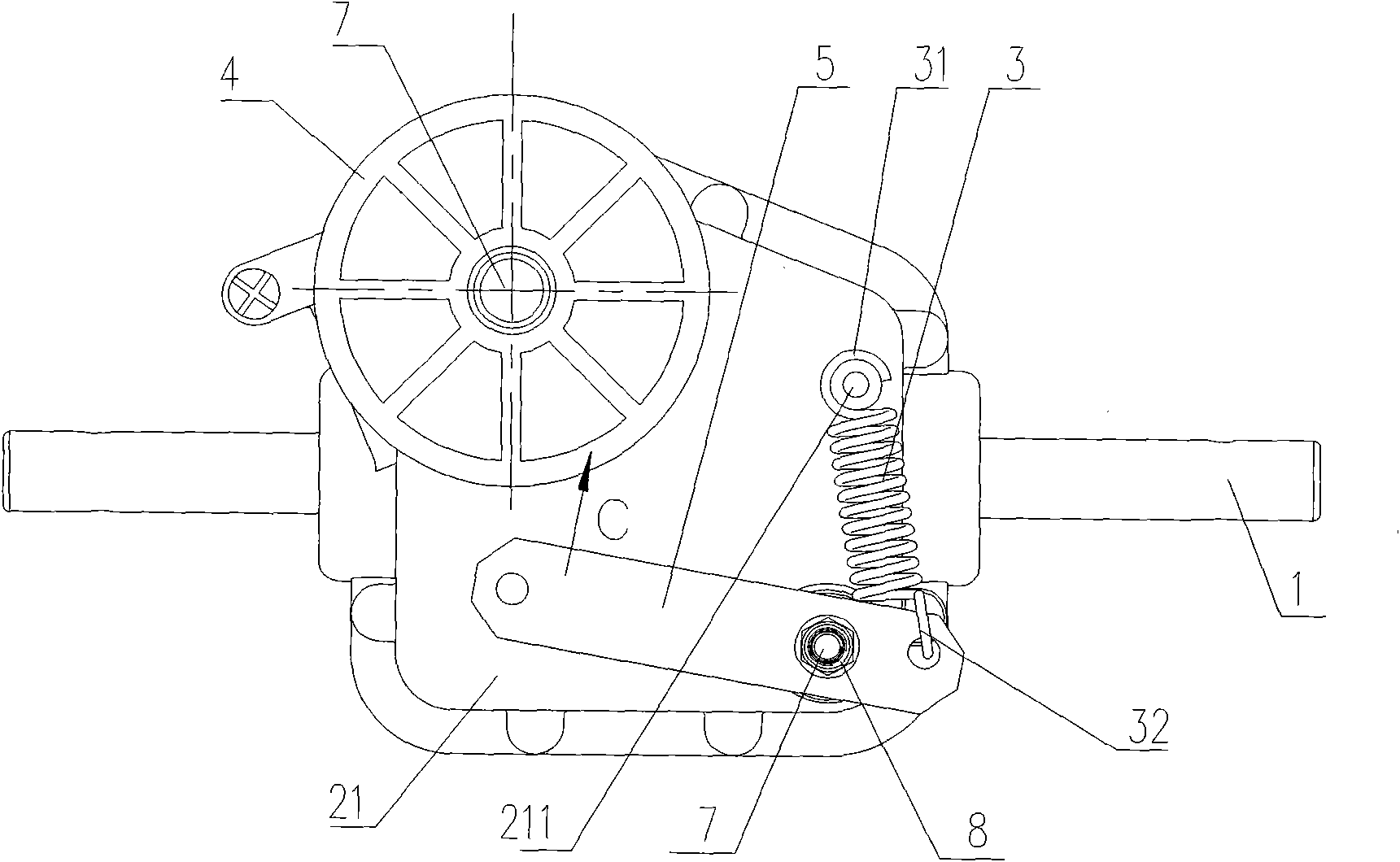
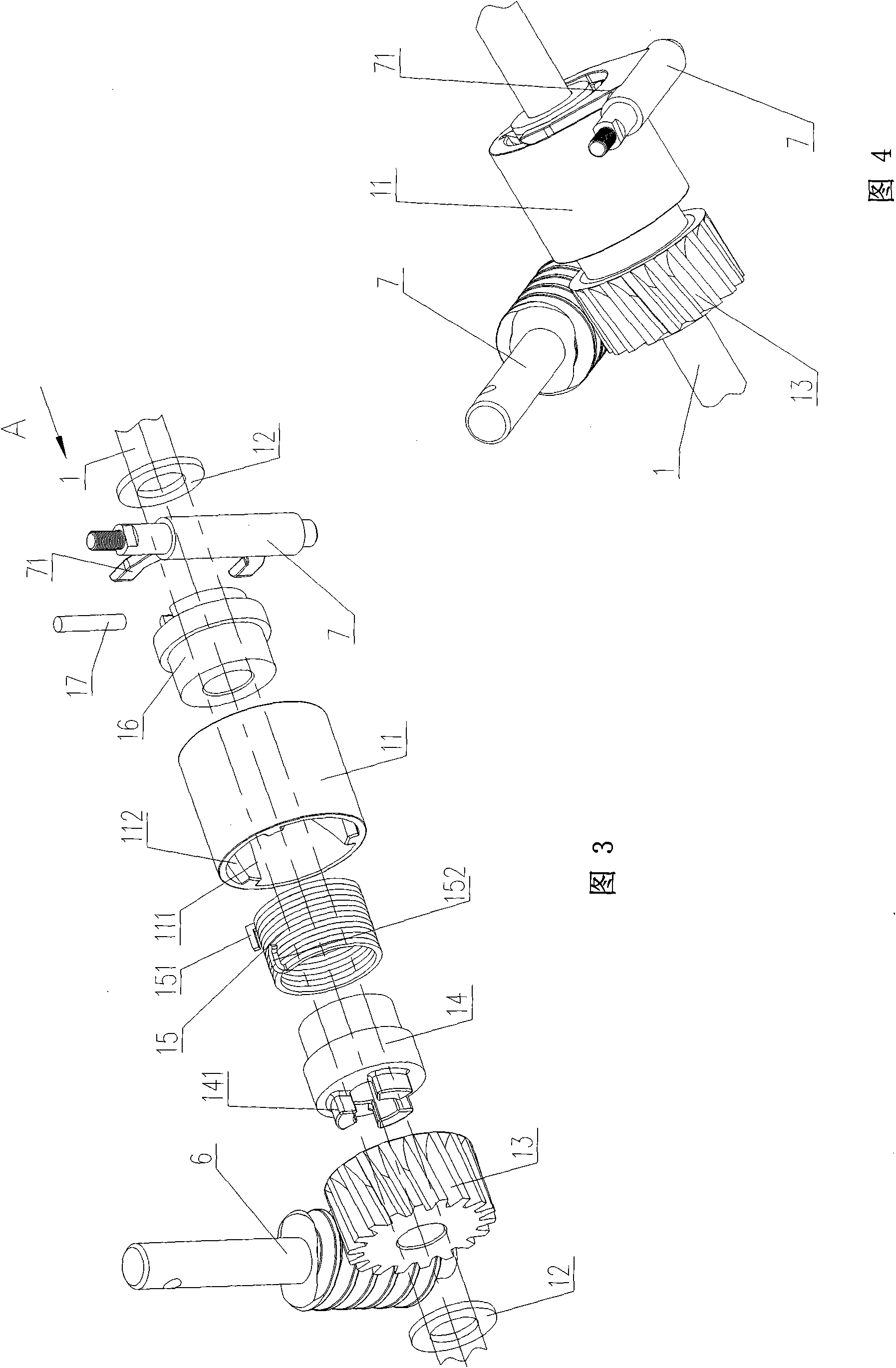
[0021] Such as Figure 1 to Figure 7 As shown, the present invention includes output shaft 1, gasket 12, worm screw 6, worm wheel 13, clutch separation shaft 7, extension spring 3, clutch swing arm 5, sliding sleeve 11, axle sleeve I 14, torsion spring 15, axle sleeve II 16. Elastic pin 17; spacer 12, worm gear 13, bushing I 14, torsion spring 15, bushing II 16 are sequentially set on the output shaft 1, and the outside of the spacer 12 is respectively provided with a The bearing seat 10, the output shaft 1 is supported on the box body 2 through the bearing seats 10 on both sides, the gasket 12 is respectively arranged between the bearing seat 10 and the worm wheel 13, the bearing seat 10 and the shaft sleeve II 16, and the sliding sleeve 11 Frequent axial movement acts as a stop back.

[0022] Such as image 3 , Figure 7 As shown, the torsion spring 15 is sleeved ...


PUM


Abstract

The invention discloses a clutch device of an output shaft of a gear-box for a lawn-mower, which comprises a spacer, a worm wheel, a shaft sleeve I, a torsional spring and a shaft sleeve II, wherein the spacer, the worm wheel, the shaft sleeve I, the torsional spring and the shaft sleeve II are sleeved on the output shaft in turn; the torsinal spring is sleeved in a sliding sleeve; two ends of the torsional spring are sleeved on the shaft sleeve I and the shaft sleeve II respectively; an inner hole of the sliding sleeve is provided with a convex rib type spiral-line wedge; vertical paws and bending paws at two ends of the torsional spring prop against an axial plane on the one side of the spiral wedge in the inner hole of the sliding sleeve and a spiral plane on the other side respectively; a worm is meshed with the worm wheel; the shaft sleeve I is radially and fixedly connected with the worm wheel; the shaft sleeve II is fixedly connected with the output shaft through an elastic pin; a clutch release shaft is vertically arranged besides the shaft sleeve II; the upper end of the clutch release shaft passes through the upper side of a box body and is fixedly connected with an clutch swing arm; two ends of a tension spring are in clasp joint with the upper side of the box body and one end of the clutch swing arm; and the other end of the clutch swing arm is hinged with a clutch operating mechanism. The clutch device has compact structure, small radial dimension; and the sliding sleeve has an integral structure, is convenient to process, assemble and maintain, so that the manufacturing cost of the device is low.

Description

technical field [0001] The invention relates to a clutch device for an output shaft of a gearbox, in particular to a clutch device for controlling the self-propelled or stopped state of a small self-propelled lawn mower, which belongs to the technical field of garden machinery. Background technique [0002] With the improvement of living standards and the need to beautify the environment, the use of lawns has grown rapidly. Whether it is municipal, residential quarters, football fields, golf courses, etc., the work of lawn maintenance has doubled. As a green maintenance facility, the lawn mower plays an important role in lawn maintenance. The power of the existing self-propelled small lawn mower engine is transmitted to the gearbox by the transmission belt, and the self-propelled or stopped mower is realized through the combination or separation of the clutch device in the gearbox. The advantages and disadvantages of the structure of the clutch device Determines the service...

Claims


Application Information

Patent Timeline
Patent Type & Authority Applications(China)
IPC IPC(8): A01D69/08
CPCF16D23/12A01D69/08
Inventor 王挺张朝杰王强
Owner JIANGSU WORLD PLANT PROTECTING MACHINERY
Why Eureka
Try Eureka