Jig

A jig and clamping block technology, which is applied in the field of jigs, can solve problems such as damage to the main board, and achieve the effect of increasing efficiency and saving assembly time

Inactive Publication Date: 2009-12-09
MITAC COMP (SHUN DE) LTD
View PDF0 Cites 12 Cited by
  • Summary
  • Abstract
  • Description
  • Claims
  • Application Information

AI Technical Summary

Problems solved by technology

The size of the inner groove of the mold used to place the heat sink is usually slightly larger than the size of the heat sink to ensure that the heat sink is easy to put in and take out. Therefore, when locking the heat sink, it is affected by the torque generated by screwing in , the heat sink is easy to rub against the inner groove wall of the mold and get stuck, resulting in damage to the heat sink and the main board after assembly due to difficulty in removal and deformation

Method used


Image

  • Jig
  • Jig

Examples


Embodiment Construction

[0014] In order to illustrate the technical content and structural features of the present invention in detail, the following will be described in detail in conjunction with the implementation and accompanying drawings.

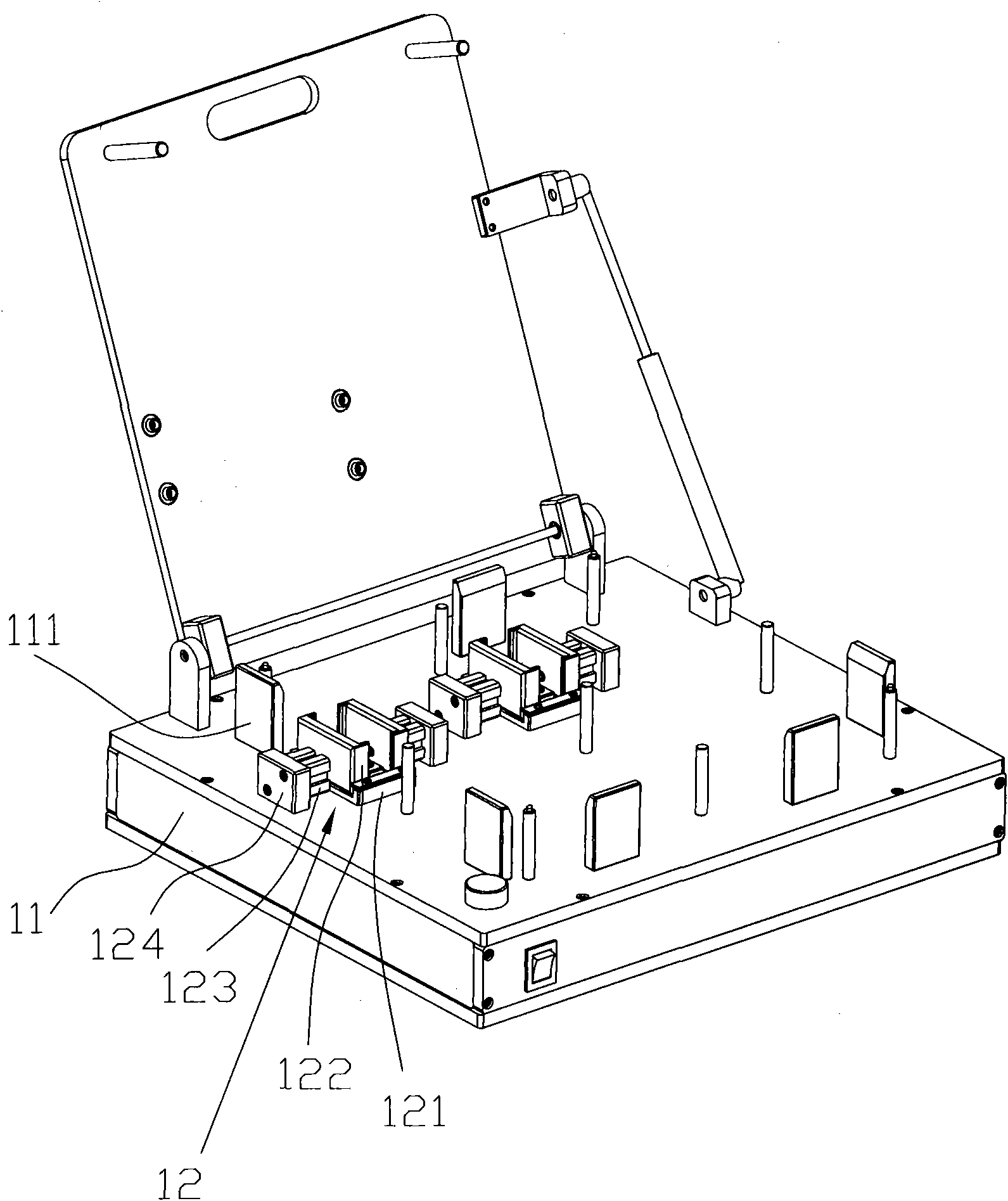
[0015] see figure 1 , is a three-dimensional assembly diagram of a preferred embodiment of the jig of the present invention. The jig includes a main box 11 provided with a circuit control device (not shown) and at least one positioning device 12 for clamping a radiator (not shown). Wherein, the main box 11 is provided with four baffles 111 for positioning the main board.

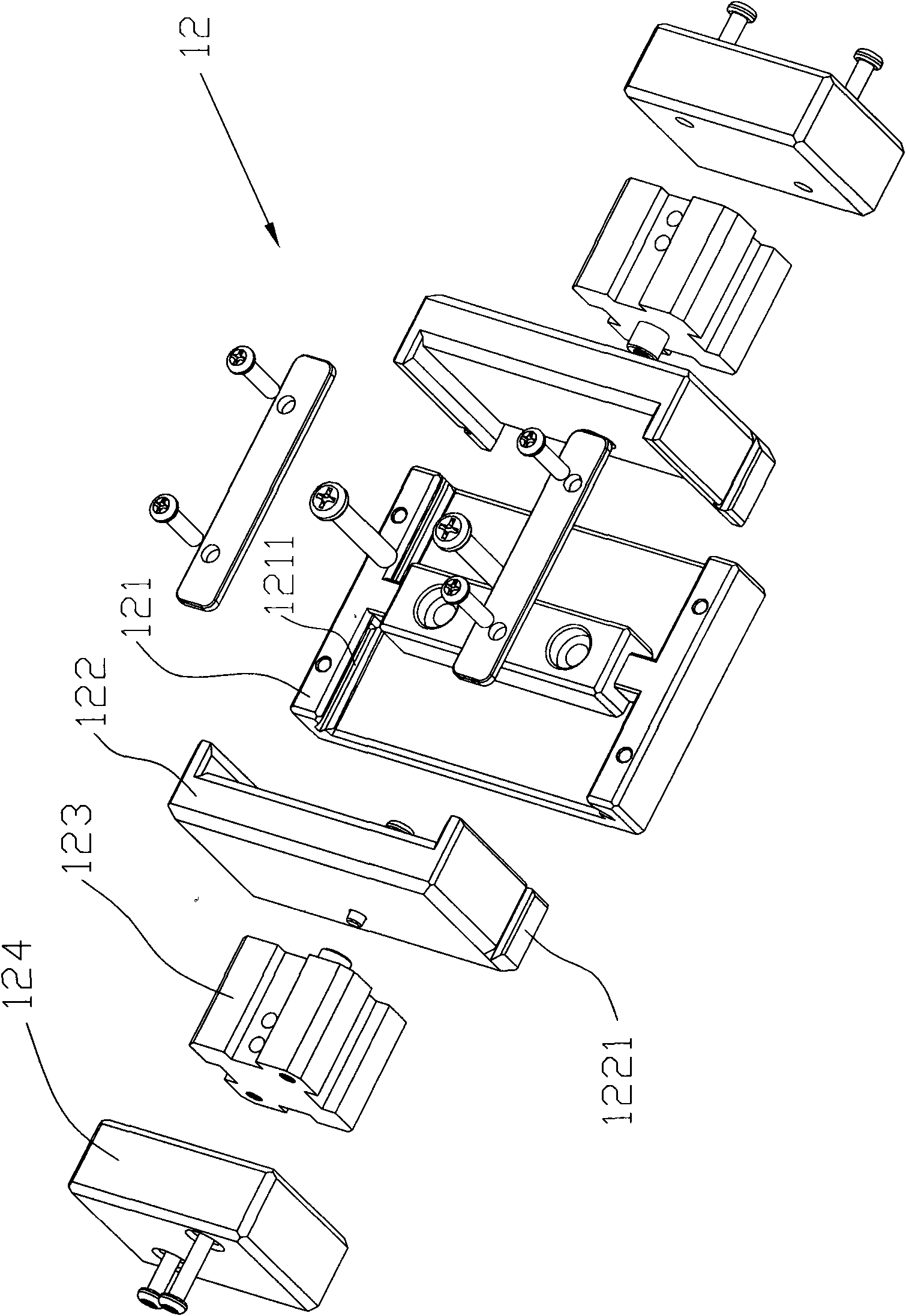
[0016] see again figure 2 , is a three-dimensional exploded schematic view of the positioning device of the jig of the present invention. The positioning device 12 includes: a concave guide positioning part 121, which is locked on the main box body 11 through a screw assembly, and guide grooves 1211 are provided on the opposite sides of the two side walls; two clamping blocks 122, each ...


PUM


Abstract

The invention relates to a jig for positioning a radiating fin so as to assemble the radiating fin, in particular to a jig for positioning a radiator assembly so as to assemble the radiator assembly. The jig comprises a main box body provided with a circuit control device and at least one positioning device for clamping a radiator. The positioning device comprises a concave guide positioning piece, two clamping blocks and two cylinders, wherein the concave guide positioning piece is fixedly locked on the main box body by a screw assembly, and both relative sides of both side walls of the concave guide positioning piece are provided with guide grooves; both corresponding positions of both side surfaces of each clamping block are provided with tenons; the two cylinders are fixedly locked to the relative side surfaces of the guide positioning piece of the clamping blocks respectively and connected to the circuit control device by a wire. The two clamping blocks are pushed by the two cylinders to move face to face or in the opposite direction so that a clamped, positioned or assembled main plate of the radiating fin is smoothly taken out; the jig can be also provided with a plurality of positioning devices for simultaneously positioning and assembling a plurality of radiating fins, thereby saving the assembly time and improving the assembly and manufacture efficiency.

Description

technical field [0001] The invention relates to a jig, in particular to a jig used to position components of a radiator for assembly. Background technique [0002] Due to the rapid development of computer and electronic technology towards the direction of strong functions and fast speed, the central processing unit will generate heat during the calculation process. The general method is to assemble a heat sink on the surface of the central processing unit, and then heat dissipation on the cooling fins. A fan is assembled to conduct the heat generated by the central processing unit to the heat dissipation fins, and then the cold air generated by the fan is blown to the gaps of several heat dissipation fins for heat dissipation. [0003] At present, when assembling the cooling fins of the small heat sink of the motherboard, most of them are fixed by screw locking. The traditional way of locking the heat sink is to first use the corresponding mold to fix the heat sink to be lo...

Claims


Application Information

Patent Timeline
Patent Type & Authority Applications(China)
IPC IPC(8): B23P21/00B25B11/00G06F1/20
Inventor 黄承禄
Owner MITAC COMP (SHUN DE) LTD
Why Eureka
Try Eureka