Sealing structure of shaft end of horizontal concrete mixer

A concrete mixer and shaft end sealing technology, which is applied in cement mixing devices, clay preparation devices, chemical instruments and methods, etc., can solve problems such as oil spillage, difficulty in selection, and damage to floating ring seals, and achieve convenient installation and disassembly. The overall structure Simple, guaranteed sealing effect

Active Publication Date: 2010-10-06
CHENGDU XINZHU CONCRETE MASCH EQUIP CO LTD
View PDF0 Cites 2 Cited by
  • Summary
  • Abstract
  • Description
  • Claims
  • Application Information

AI Technical Summary

Problems solved by technology

[0004] 2. The working environment of the mixer where the O-ring is located is extremely harsh, and there are fine particles of mortar;
[0005] 3. The material of the floating ring O-ring is not resistant to alkali, once the sealing form in front of the floating ring seal is damaged, the floating ring seal will be damaged soon;
[0006] 4. The processing precision of the floating ring is very high, the circumferential rotation speed is relatively high during use, and the installation and matching dimension precision is high;
[0007] 5. It is difficult to determine the holding pressure of some forming seals, and it is not easy to maintain. If the maintenance is not done properly, there will be grease overflow or no grease entering the lubrication
[0008] As mentioned above, it is difficult to choose the combined sealing form based on the floating ring seal. From the perspective of the actual practical process and installation and maintenance, it is not easy to take into account the advantages of multiple parties.

Method used


Image

  • Sealing structure of shaft end of horizontal concrete mixer
  • Sealing structure of shaft end of horizontal concrete mixer

Examples


Embodiment Construction

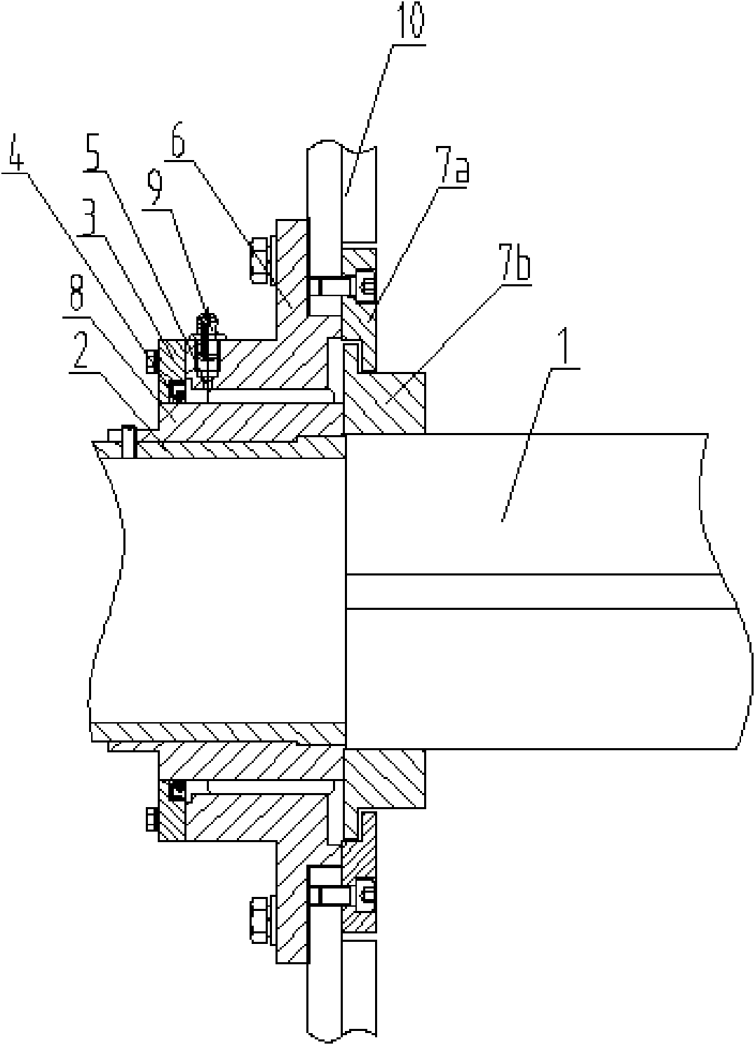
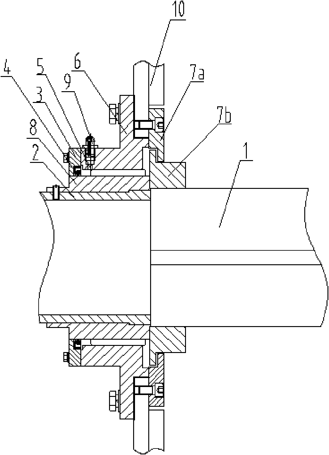
[0023] Example: as figure 1 Shown: a shaft end sealing structure of a horizontal concrete mixer, including a main shaft 1, a mixer housing 10, a shaft sleeve 2 fixed on the outer ring of the main shaft 1, and a spiral body 8 fixed on the outer ring of the shaft sleeve 2 The spiral body 8 is fitted with a sealing jacket 6 with an "L" shape in cross-section, and one side of the "L"-shaped sealing jacket forms a spiral channel with the spiral body 8, and the other side is attached to the mixer On the outer wall of the housing 10, an oil inlet hole 5 is opened on the sealing outer casing 6, and an end cap 3 is arranged on the outer end surface of the sealing outer casing 6, and the end cap 3 is sleeved on the spiral body 8 and the spiral channel The outer end opening of the mixer housing 2 is fixed with a first wear-resistant block 7a, and a second wear-resistant block 7b is arranged below the first wear-resistant block 7a, and the first wear-resistant block 7a is connected to the...


PUM


Abstract

The invention discloses a sealing structure of a shaft end of a horizontal concrete mixer, which comprises a main machine shaft(1) and a mixer shell(2), a shaft sleeve(2) is fixed on an outer ring of the main machine shaft(1), a spiral body(8) is fixed on an outer ring of the shaft sleeve(2), wherein the spiral body(8) is sleeved with a sealing outer sleeve(6) with an L-shaped cross section, a spiral channel is formed between one side of the sealing outer sleeve with the L-shaped cross section and the spiral body(8), and the other side of the sealing outer sleeve is attached to the outer wallof the mixer shell(2); the sealing outer sleeve(6) is provided with an oil inlet(5), and the outer end face of the sealing outer sleeve(6) is provided with an end cover(3); and the end cover(3) is sleeved on the spiral body(8) and seals an outer end opening of the spiral channel. The sealing structure has the advantages of simple overall structure, convenient assembly and disassembly and long service life.

Description

technical field [0001] The invention belongs to the field of concrete mixer equipment, and in particular relates to a shaft end sealing structure of a horizontal concrete mixer. Background technique [0002] At present, the main engine shaft end sealing structure of the mixer mainly includes: ① the sealing structure formed by the labyrinth and the floating ring, ② the sealing structure formed by the air seal, the formed packing, and the floating ring, and ③ the sealing structure formed by the formed packing and the floating ring, so the floating ring seal It is a commonly used sealing method for mixers. The traditional sealing structure, especially the floating ring seal has the following disadvantages: [0003] 1. The O-ring adjustment in the floating ring seal is small, no more than 2mm; [0004] 2. The working environment of the mixer where the O-ring is located is extremely harsh, and there are fine particles of mortar; [0005] 3. The material of the floating ring O-...

Claims


Application Information

Patent Timeline
Patent Type & Authority Patents(China)
IPC IPC(8): B28C5/08
Inventor 郭文胜朱博
Owner CHENGDU XINZHU CONCRETE MASCH EQUIP CO LTD
Why Eureka
Try Eureka