Illuminant

A lighting body and main body technology, applied in the direction of lighting devices, lighting and heating equipment, parts of lighting devices, etc., can solve the problems of inaccessibility, increased power consumption, inability to obtain light distribution, etc., and achieve the effect of avoiding obstruction

Inactive Publication Date: 2009-12-09
TAMURA KK
View PDF1 Cites 8 Cited by
  • Summary
  • Abstract
  • Description
  • Claims
  • Application Information

AI Technical Summary

Problems solved by technology

[0005] However, as mentioned above, the light distribution intensity of the LED toward the upper direction has a directivity of about 120° above the light emitting surface. If the amount of light directly above is set to 1, the 120° direction becomes 1 / 2 of the light amount. Light distribution toward the back cannot be obtained in a single LED
That is, it cannot be obtained as Figure 15 As shown in the incandescent lamp, the wide light distribution characteristics including the light distribution toward the back of the light source make it difficult to use surface mount LEDs to form light bulbs
[0006] In addition, as described above, since the power consumption per LED unit increases due to the increase in the light beam, it is necessary to increase the outer shape of the heat dissipation structure such as a heat sink, and there is a problem that the outer shape interferes with the light distribution from the LED.

Method used


Image

  • Illuminant
  • Illuminant
  • Illuminant

Examples


Embodiment approach

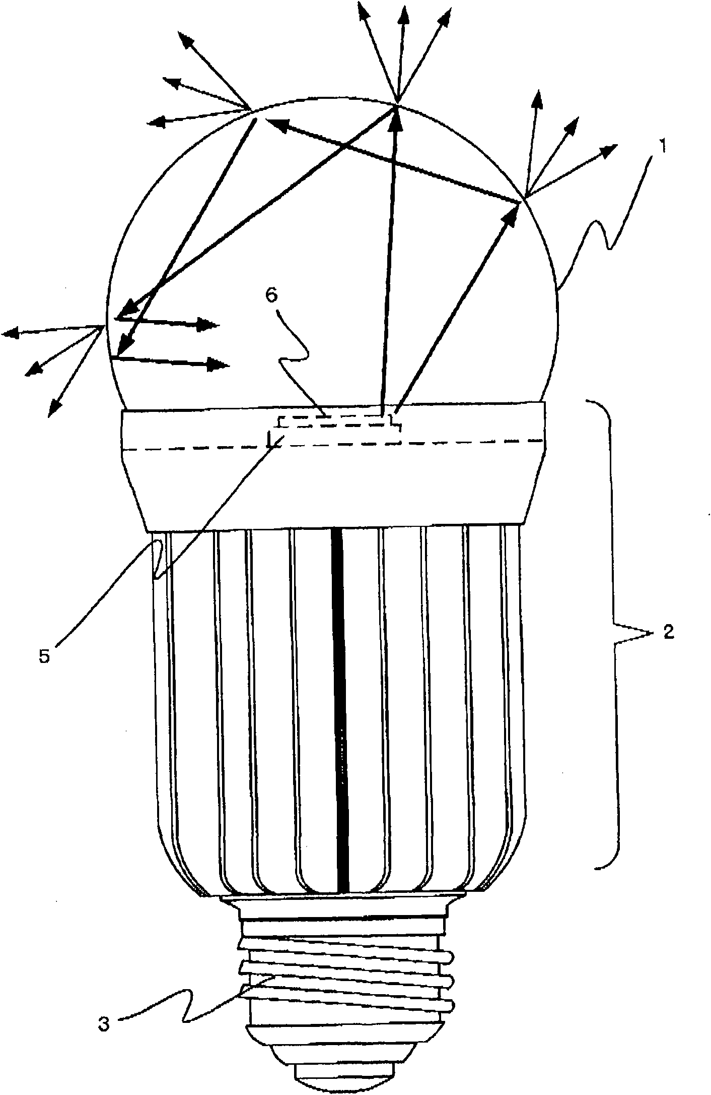
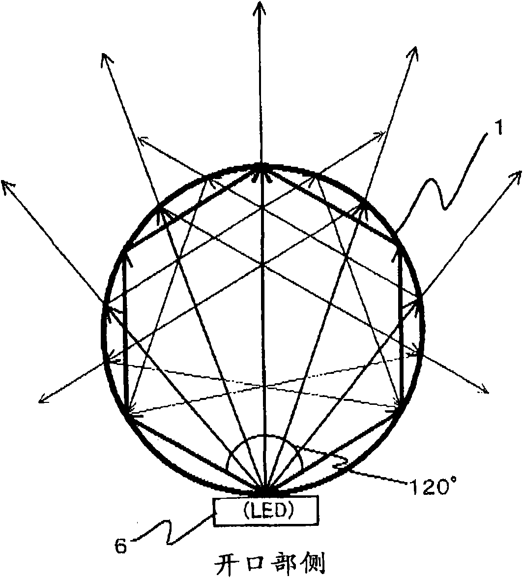
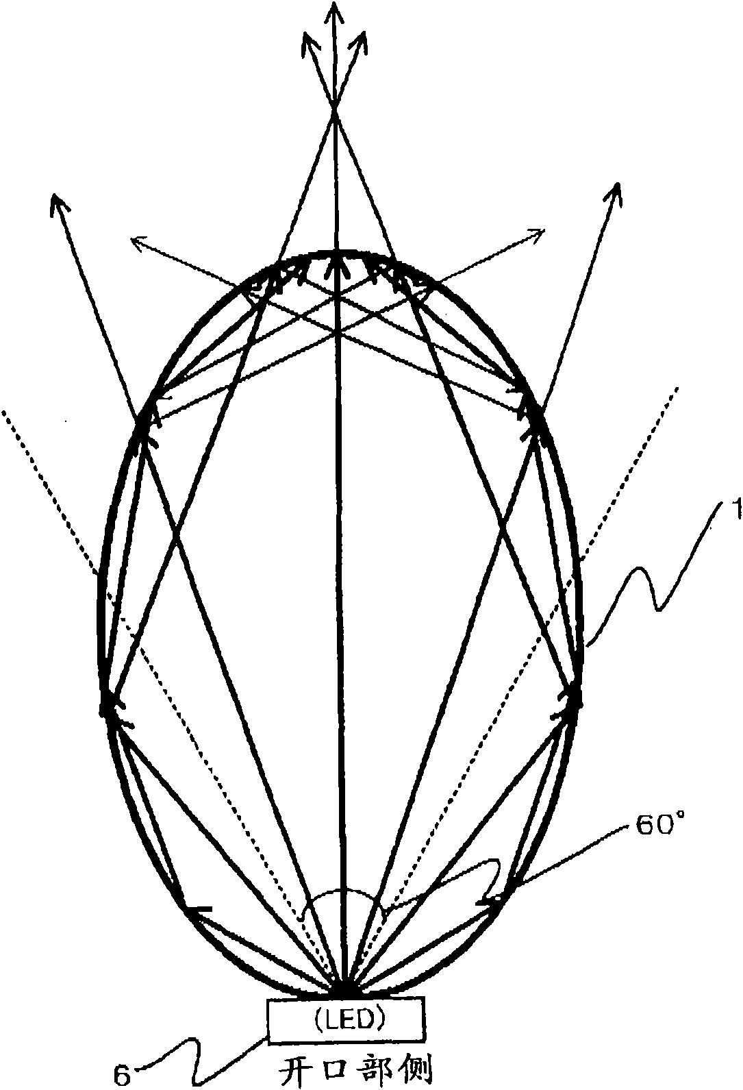
[0037] Second, refer to Figure 1-13 , the best mode for carrying out the present invention (hereinafter referred to as "this embodiment") will be described below. In addition, in figure 1 In, an example of the structure of the illuminating body related to this embodiment is shown, and in Figure 2-11 In , the angles of reflection and total reflection are calculated from the angle of incident light incident on the cover that changes according to various cover shapes and LED installation locations, and the state of the light traveling direction is indicated by arrows. Figure 13 The state of diffusion of light that occurs together with reflection inside the cover when the light reaches the cover is shown. Figure 14 The 120° directivity of an LED as a point light source is shown.

[0038] [1. Structure example]

[0039] Illumination bodies related to the present invention, such as figure 1 As shown, there is a cover 1 covering LED6 (in figure 1 In, as an example, a part...

Embodiment 4

[0049] Embodiment 4 is the same as Embodiment 1. The shape of the partially spherical cover 1 in which the opening is mounted on the cover mounting part 4 of the main body 2 is assumed to be spherical, as Figure 5 As shown, the LED 6 is arranged at a position approximately 1 / 4 of the distance from the spherical surface of the cover 1 toward the center of the cover 1 . That is, the LED 6 is provided at a position approximately 3 / 4 of the radius of the cover 1 and on the opening side of the cover 1 .

[0050] In Embodiment 5, as in Embodiments 1 and 4, the shape of the partially spherical cover 1 in which the opening is attached to the cover mounting portion 4 of the main body 2 is assumed to be spherical, as Figure 6 As shown, the LED 6 is provided at a position approximately midway between the spherical surface of the cover 1 and the center of the cover 1 . That is, the LED 6 is provided at a position approximately 1 / 2 of the radius of the cover 1 and on the opening side of...

Embodiment 7

[0052] Embodiment 7 is the same as Embodiments 1, 4 to 6. The shape of the partially spherical cover 1 in which the opening is mounted on the cover mounting part 4 of the main body 2 is assumed to be spherical, as shown in Figure 8 As shown, the LED 6 is arranged in the center of the spherical cover 1 .


PUM


Abstract

The invention provides an illuminant. The topic of the invention is to provide the semitransparent illuminant in a shape of enclosed globe shade with function of radiation that can realize grading property in wide range from a light source and avoid barrier led by radiation structure. The shape of the shade is spherical. An LED (6) is disposed on a spherical surface of the shade (1). The embodiment (4) in a center of the shade (1) is an optimal structure that the grading property in wide range is realized like electric incandescent lamps. According to the result, the optimal structure of shape of the shade (1) of the grading property in wide range and position of the LED (6) with least perfect reflection and most diffuse reflection in the shade (1) is realized.

Description

technical field [0001] The present invention relates to an illuminating body with a semi-transparent spherical cover with a diffusion function. It relates to the combination of the shape of the cover, the position of the LED and the diffusion and internal diffuse reflection caused by the diffusing function. Spotless and evenly illuminated technology. Background technique [0002] In recent years, surface mount LEDs have been used as light sources for lighting. The surface mount LED is characterized in that the light distribution toward the upper direction is strong because the surface mount LED has high luminance and strong directivity. Such as Figure 14 As shown in , in general, most of them have a directivity of about 120° above the light emitting surface. [0003] In addition, due to the increasing trend of high-beam and miniaturization of LED development in recent years, the power consumption of each single LED increases due to high-beam, so it is also proposed to use...

Claims


Application Information

Patent Timeline
Patent Type & Authority Applications(China)
IPC IPC(8): F21V19/00F21V5/00H01L33/00F21Y101/02F21V3/02F21V17/00F21V23/00F21V29/00F21Y103/37
Inventor 松尾敏稻田宪弘
Owner TAMURA KK
Why Eureka
Try Eureka