Optical fiber laser detector capable of being used on land and underwater
A fiber laser and fiber laser technology, applied in seismic signal receivers, etc., to eliminate the influence of hydrostatic pressure, reduce lateral sensitivity, and reduce volume
- Summary
- Abstract
- Description
- Claims
- Application Information
AI Technical Summary
Problems solved by technology
Method used
Image

Examples
Embodiment 1
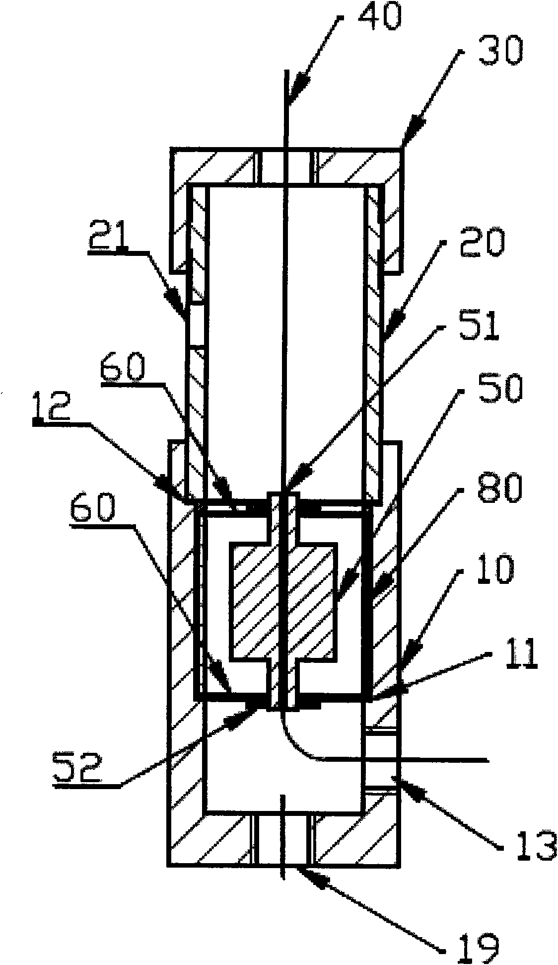
[0051] Please refer to figure 1 , Figure 6-12 , the fiber laser detector that can be used on land and underwater includes: a main body tube 10 for installing a diaphragm 60 and a mass block 50; an extension tube 20 for reserving enough space for the fiber laser 40 and compressing the diaphragm 60; the end cap 30 is used to protect the inside of the sensor, draw out the laser 40, and fix one end of the fiber laser 40; the fiber laser 40 is used to detect seismic wave signals; two diaphragms 60 are used as limiting elements to control the detector Frequency response characteristics and sensitivity, and limit the lateral displacement of the mass block 50 to reduce the lateral sensitivity of the geophone; the mass block 50 installed between the diaphragms 60, as an inertial element, is used to increase the fiber laser 40 caused by the seismic wave signal axial strain, and fix the other end of the fiber laser 40; the hole 63 on the diaphragm 60 is used to communicate with various...
Embodiment 2
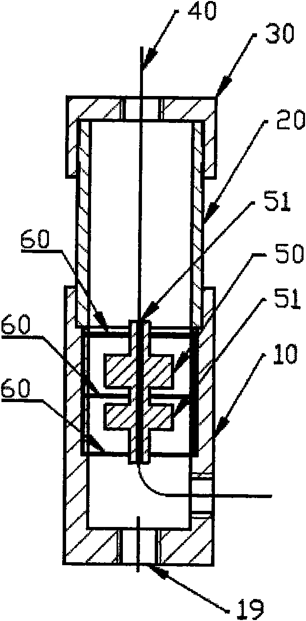
[0064] Please refer to figure 2 , Figure 6-12 , the fiber laser detector that can be used on land and underwater includes: a main body tube 10 for installing a diaphragm 60 and a mass block 50; an extension tube 20 for reserving enough space for the fiber laser 40 and compressing the diaphragm 60; the end cap 30 is used to protect the inside of the sensor, draw out the laser 40, and fix one end of the fiber laser 40; the fiber laser 40 is used to detect seismic wave signals; two diaphragms 60 are used as limiting elements to control the detector Frequency response characteristics and sensitivity, and limit the lateral displacement of the mass block 50 to reduce the lateral sensitivity of the geophone; the mass block 50 installed between the diaphragms 60, as an inertial element, is used to increase the fiber laser 40 caused by the seismic wave signal axial strain, and fix the other end of the fiber laser 40; the hole 63 on the diaphragm 60 is used to communicate with variou...
Embodiment 3
[0078] Please refer to Figure 4 , Figure 6-12 , the fiber laser detector that can be used on land and underwater includes: a main body tube 10 for installing a diaphragm 60 and a mass block 50; an extension tube 20 for reserving enough space for the fiber laser 40 and compressing the diaphragm 60; the end cap 30 is used to protect the inside of the sensor, draw out the laser 40, and fix one end of the fiber laser 40; the fiber laser 40 is used to detect seismic wave signals; two diaphragms 60 are used as limiting elements to control the detector Frequency response characteristics and sensitivity, and limit the lateral displacement of the mass block 50 to reduce the lateral sensitivity of the geophone; the mass block 50 installed between the diaphragms 60, as an inertial element, is used to increase the fiber laser 40 caused by the seismic wave signal axial strain, and fix the other end of the fiber laser 40; the hole 63 on the diaphragm 60 is used to communicate with variou...
PUM
 Abstract
Description
Claims
Application Information
 - R&D Engineer
- R&D Manager
- IP Professional
- Industry Leading Data Capabilities
- Powerful AI technology
- Patent DNA Extraction
Browse by: Latest US Patents, China's latest patents, Technical Efficacy Thesaurus, Application Domain, Technology Topic.
© 2024 PatSnap. All rights reserved.Legal|Privacy policy|Modern Slavery Act Transparency Statement|Sitemap