Liquid metal cutting magnetic line type power generating device based on human body energy drive
A technology of liquid metal and human body energy, applied in the direction of electromechanical devices, electrical components, etc., can solve problems such as limited progress, achieve the effect of improving power generation capacity and simple structure
- Summary
- Abstract
- Description
- Claims
- Application Information
AI Technical Summary
Problems solved by technology
Method used
Image
Examples
Embodiment 1
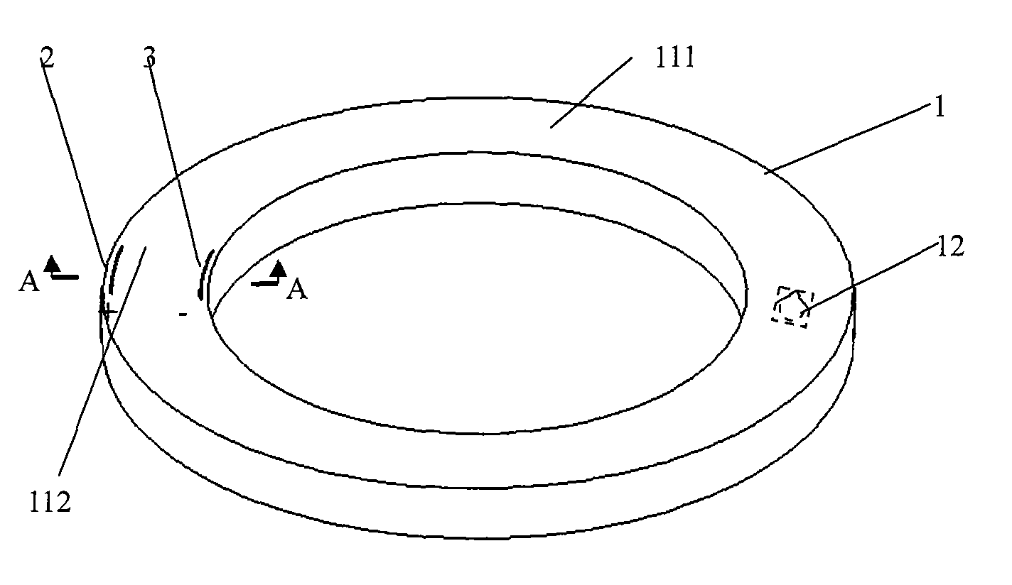
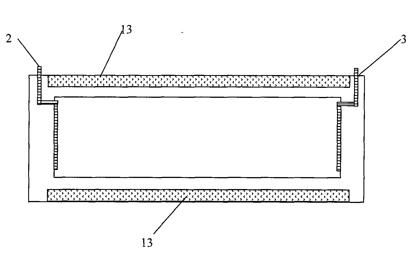
[0028] attached figure 1 It is a structural schematic diagram of the present invention; figure 2 for figure 1 The A-A sectional schematic diagram; As can be seen from the figure, the liquid metal cutting magnetic field line type power generation device driven by human body energy of the present invention includes:
[0029] At least one hollow sealed annular channel main body 1 containing liquid metal, the annular channel 111 of the hollow sealed annular channel main body 1 is equipped with a one-way valve 12 to control the flow direction of liquid metal;
[0030] at least one fluid power generation unit 112;
[0031] The fluid power generation unit 112 is composed of a positive plate 2 and a negative plate 3 that are placed oppositely on the inner wall of the annular channel 111 of the hollow sealed annular channel main body 1; and
[0032] A pair of permanent magnets 13 inlaid on the upper and lower end surfaces of the annular channel main body 1 or located above and belo...
Embodiment 2
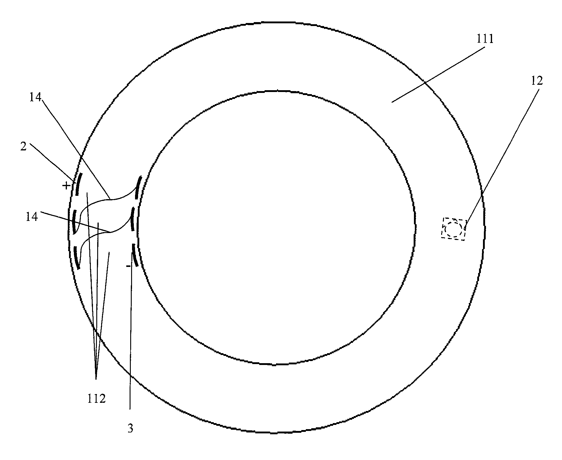
[0042] as attached image 3 As shown, this embodiment is a power generation device in which a plurality of fluid power generation units are combined. The number of fluid power generation units included in this embodiment can be one to one million, and the positive plate 2 and the negative plate 3 of the fluid power generation unit are connected by a wire 14; in this embodiment, they are connected in series, and the previous stage of fluid power generation The negative plate of the unit is connected to the positive plate of the next-stage fluid power generation unit; the positive plate of the first-stage fluid power generation unit is the positive pole output by the entire power generation device, and the negative plate of the last-stage fluid power generation unit is the negative pole of the entire power generation device. It can also be connected in parallel, and the positive and negative plates of the fluid power generation units at all levels are connected together through ...
Embodiment 3
[0047] attached Figure 4 Schematic diagram of the structure of a power generation device in which multiple sealed hollow annular channel bodies are stacked together; Figure 5 for Figure 4 The B-B profile;
[0048] The number of independent annular passages in this embodiment may be 1-10000; at least one fluid power generation unit is placed in each independent annular passage; the fluid power generation units between the independent annular passages are connected by wires 14 . The connection mode in this embodiment may be series connection, parallel connection, or mixed connection of series and parallel.
[0049] The permanent magnets in this embodiment can be NdFeB magnets, ferrite magnets, cobalt-nickel magnets, nano-NdFeB magnets, nano-ferrite magnets, nano-CoNi magnets, ferromagnets, cobalt magnets or nickel magnets. It can be combined with the annular channel by pasting, inlaying, spraying, and depositing.
[0050] The permanent magnets in this embodiment can be lo...
PUM
 Abstract
Description
Claims
Application Information
 - R&D
- Intellectual Property
- Life Sciences
- Materials
- Tech Scout
- Unparalleled Data Quality
- Higher Quality Content
- 60% Fewer Hallucinations
Browse by: Latest US Patents, China's latest patents, Technical Efficacy Thesaurus, Application Domain, Technology Topic, Popular Technical Reports.
© 2025 PatSnap. All rights reserved.Legal|Privacy policy|Modern Slavery Act Transparency Statement|Sitemap|About US| Contact US: help@patsnap.com


