Backlash converter

A technology of flyback converter and transformer, which is applied in the direction of instruments, adjusting electric variables, converting DC power input to DC power output, etc. It can solve the problems of low switching loss and high switching loss, and reduce conduction loss and cut-off loss , the effect of reducing voltage loss

Inactive Publication Date: 2009-12-09
INNOCOM TECH SHENZHEN +1
View PDF0 Cites 6 Cited by
  • Summary
  • Abstract
  • Description
  • Claims
  • Application Information

AI Technical Summary

Problems solved by technology

[0011] In order to solve the problem of high switching loss of the prior art flyback converter, it is necessary to provide a flyback converter with lower switching loss

Method used


Image

  • Backlash converter
  • Backlash converter

Examples


Embodiment Construction

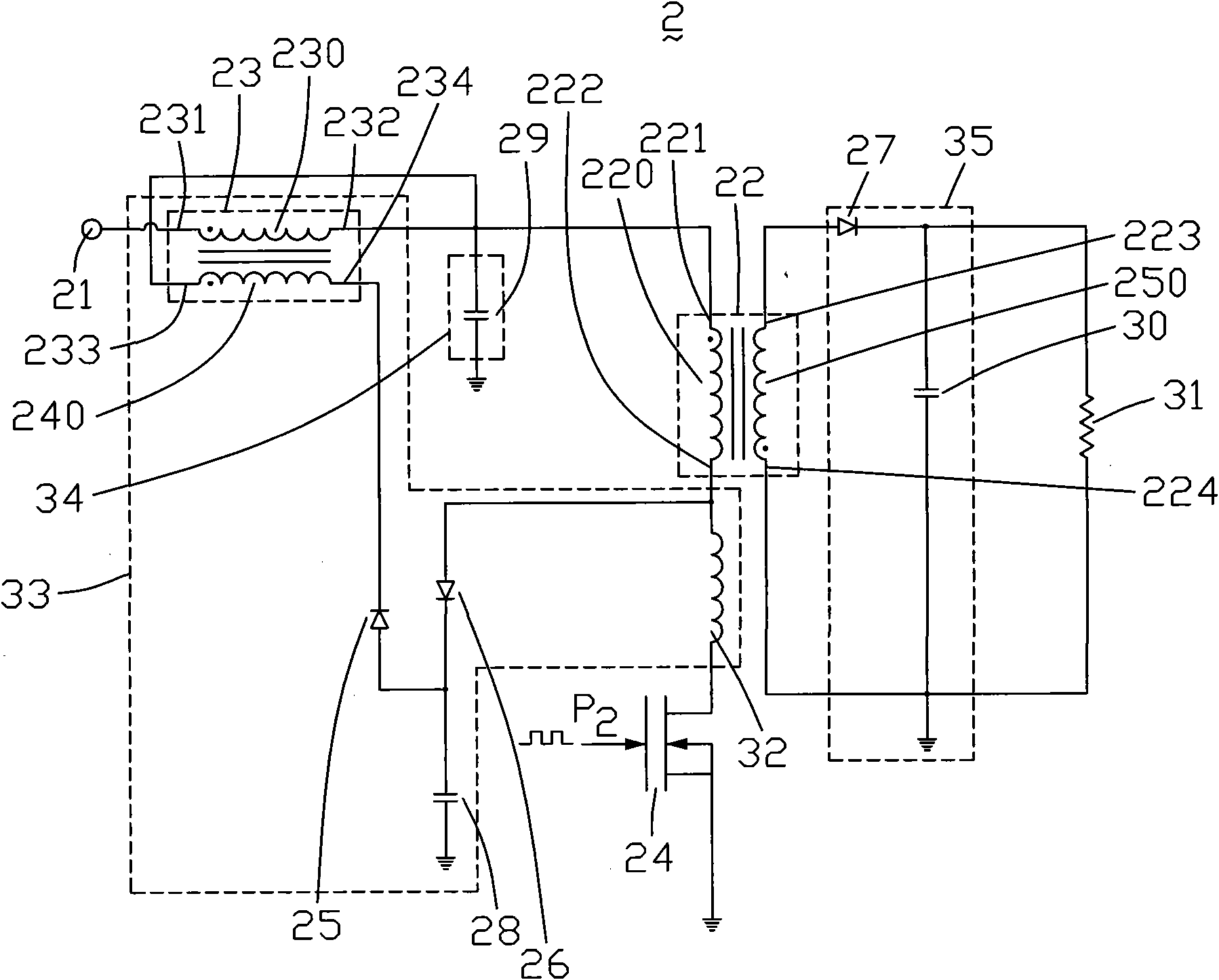
[0017] see figure 2 , is a circuit structure diagram of a preferred embodiment of the flyback converter of the present invention. The flyback converter 2 includes a voltage input terminal 21 , a first transformer 22 , a switch tube 24 , an auxiliary circuit 33 , a filter circuit 34 , a rectification filter circuit 35 and a load 31 . The voltage input terminal 21 is a DC voltage input terminal, and the switch tube 24 is an N-channel enhancement type field effect transistor. The load 31 is a resistor.

[0018] The first transformer 22 includes a first primary winding 220 and a first secondary winding 250 . The first primary winding 220 includes a first end 221 and a second end 222 . The first secondary winding 250 includes a third end 223 and a fourth end 224 . The first end 221 and the fourth end 224 have the same name.

[0019] The auxiliary circuit 33 includes a second transformer 23 , a first diode 25 , a second diode 26 , a first capacitor 28 and an inductor 32 . The...


PUM


Abstract

The invention relates to a backlash converter comprising a voltage input terminal, a first transformer, a switching tube, a load and an auxiliary circuit, wherein the first transformer comprises a first primary winding and a first secondary winding, and the first secondary winding is used for supplying voltage to the load; the auxiliary circuit comprises a first diode, a second diode, a capacitor and a second transformer; the second transformer comprises a second primary winding and a second secondary winding; the voltage input terminal is connected in series with a drain electrode of the switching tube through the second primary winding and the first primary winding; a source electrode of the switching tube is grounded, and a grid electrode of the switching tube is used for receiving a pulse; a positive electrode of the first diode is grounded through the capacitor, and a negative electrode of the first diode is connected with the homonymic terminal of the first primary winding after being connected in series with the second secondary winding; a negative electrode of the second diode is grounded through the capacitor, and a positive electrode of the second diode is electrically connected with the drain electrode of the switching tube.

Description

technical field [0001] The invention relates to a flyback converter. Background technique [0002] Flyback converters have been widely used in DC voltage circuits with multiple outputs due to their simple circuit and high output efficiency. [0003] see figure 1 , is a circuit structure diagram of a prior art flyback converter. The flyback converter 1 includes a voltage input terminal 11 , a transformer 12 , a switch tube 13 , a diode 14 , a capacitor 15 and a load 16 . The voltage input terminal 11 is a DC voltage input terminal, and the switch tube 13 is an N-channel enhancement type field effect transistor. [0004] The transformer 12 includes a primary winding 120 and a secondary winding 130 . The primary winding 120 includes a first end 121 and a second end 122 . The secondary winding 130 includes a third end 123 and a fourth end 124 . The first end 121 and the fourth end 124 have the same name. [0005] The voltage input end 11 is connected to the first end 121 ...

Claims


Application Information

Patent Timeline
Patent Type & Authority Applications(China)
IPC IPC(8): H02M3/335
Inventor 郑接见周通
Owner INNOCOM TECH SHENZHEN
Why Eureka
Try Eureka