Domain split network and method for obtaining network topology map of domain split network
A technology of network topology diagram and sub-domain network, which is applied in the field of packet data network, can solve the problem of heavy burden on a single control and management device, and achieve the effect of load sharing and burden reduction
- Summary
- Abstract
- Description
- Claims
- Application Information
AI Technical Summary
Problems solved by technology
Method used
Image
Examples
Embodiment 1
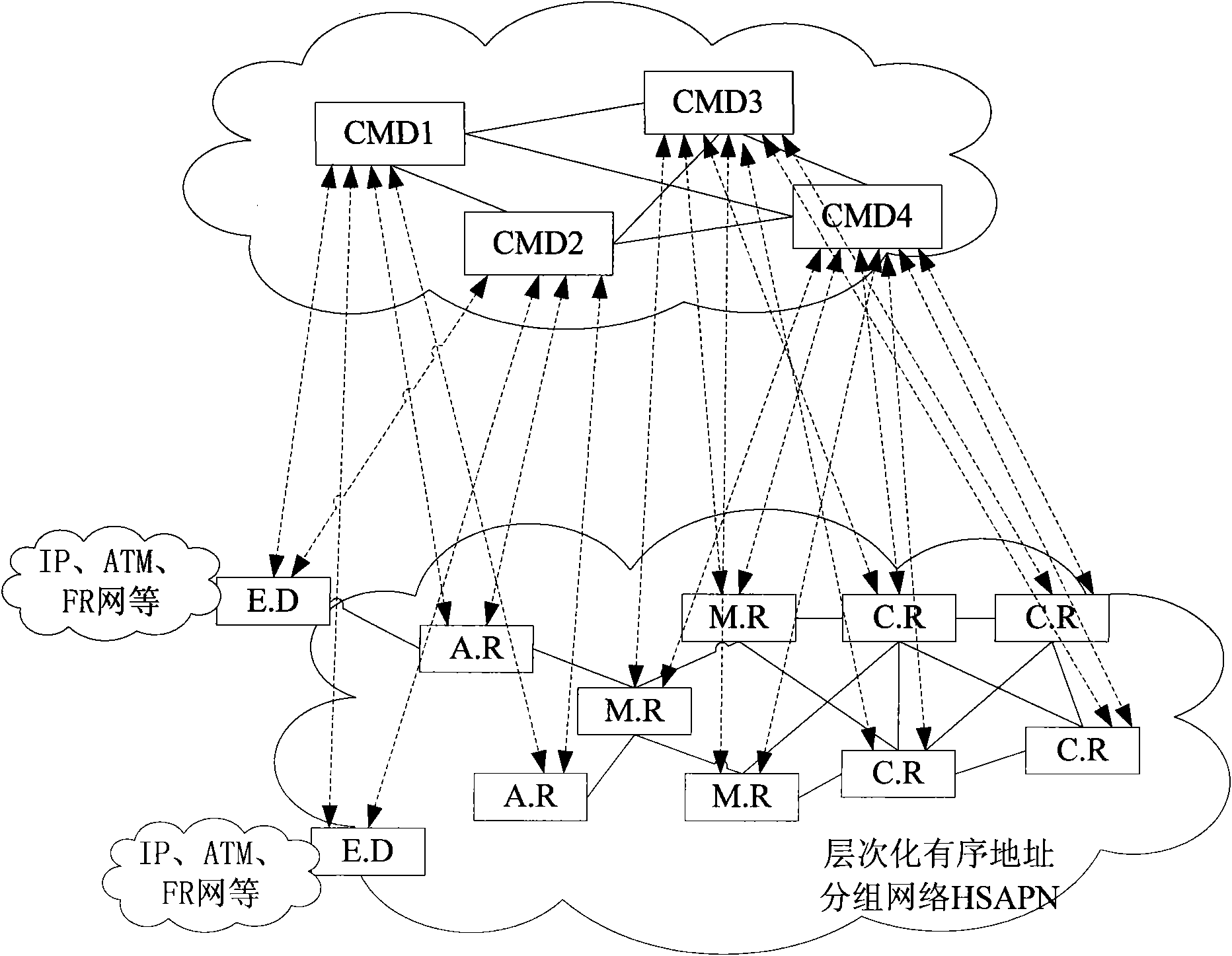
[0049] see image 3 , when the network scale is large, the entire network can be divided into several control and management domains. The division of control and management domains can be divided according to the specific situation, according to level, region, or a combination of level and region.
[0050] Since HSAPN adopts a hierarchical and orderly addressing method and hierarchical routing, a certain path can be determined according to the address, such as Figure 4 Shown is a schematic diagram of a hierarchical routing network. HSAPN addresses are addressed in a hierarchical manner according to operators and regions, so the addresses are hierarchical and orderly. For example, A.B.C.D is a form of HSAPN addresses. In this example, the network is divided into 4 levels, A, Sections B, C, and D (can also be divided into 5 sections and 6 sections according to the situation. The encoding format and length of each section can be set according to the situation. It is recommended ...
Embodiment approach
[0064] As another implementation manner, the above-mentioned control management device includes:
[0065] An information collection module, configured to collect link state advertisement information sent by routers within the jurisdiction;
[0066] The area network topology map generation module is used to generate the network topology map of the area under the jurisdiction of the control device according to the received link state notification information of the area under its jurisdiction;
[0067] The second synchronization module is used to synchronize information between the generated network topology diagram of the jurisdiction area of the control device and the network topology diagrams of the jurisdiction regions of other domain control and management devices, so as to obtain the network topology diagram of the entire network.
[0068] The above-mentioned control and management equipment may also include:
[0069] The intercommunication module is configured to notif...
Embodiment 2
[0076] After the control and management equipment is deployed, each domain is under the control and management of the CMD of the domain, and the network topology diagram is established through the information synchronization between the CMDs, such as Figure 8 As shown, taking the HSAPN network as an example, the embodiment of the present invention provides a method for obtaining a network topology map of a sub-area network, and the steps are as follows:
[0077] Step 201: Each domain establishes a control management channel network between the CMD and each HSAPN router in the area under the jurisdiction of the CMD.
[0078] The embodiment of the present invention provides the following two technical solutions to realize the establishment of the control management channel network between the CMD and each HSAPN router in the area under its jurisdiction:
[0079] 1. Establish an in-band control management channel network
[0080] Before the entire network starts running, a rout...
PUM
 Abstract
Description
Claims
Application Information
 - R&D
- Intellectual Property
- Life Sciences
- Materials
- Tech Scout
- Unparalleled Data Quality
- Higher Quality Content
- 60% Fewer Hallucinations
Browse by: Latest US Patents, China's latest patents, Technical Efficacy Thesaurus, Application Domain, Technology Topic, Popular Technical Reports.
© 2025 PatSnap. All rights reserved.Legal|Privacy policy|Modern Slavery Act Transparency Statement|Sitemap|About US| Contact US: help@patsnap.com


