Metering device

A technology of a metering device and a metering device, which is applied in the directions of feeding device, injection device, injection device, etc., can solve the problem of inability to generate gaseous reactants without delay, and achieve improved atomization and distribution, reliable cost, and simple structure. Effect

Inactive Publication Date: 2009-12-09
ROBERT BOSCH GMBH
View PDF2 Cites 5 Cited by
  • Summary
  • Abstract
  • Description
  • Claims
  • Application Information

AI Technical Summary

Problems solved by technology

Conventional vaporizers are not able to produce the corresponding quantities of gaseous reactants without delay

Method used


Image

  • Metering device
  • Metering device

Examples


Embodiment Construction

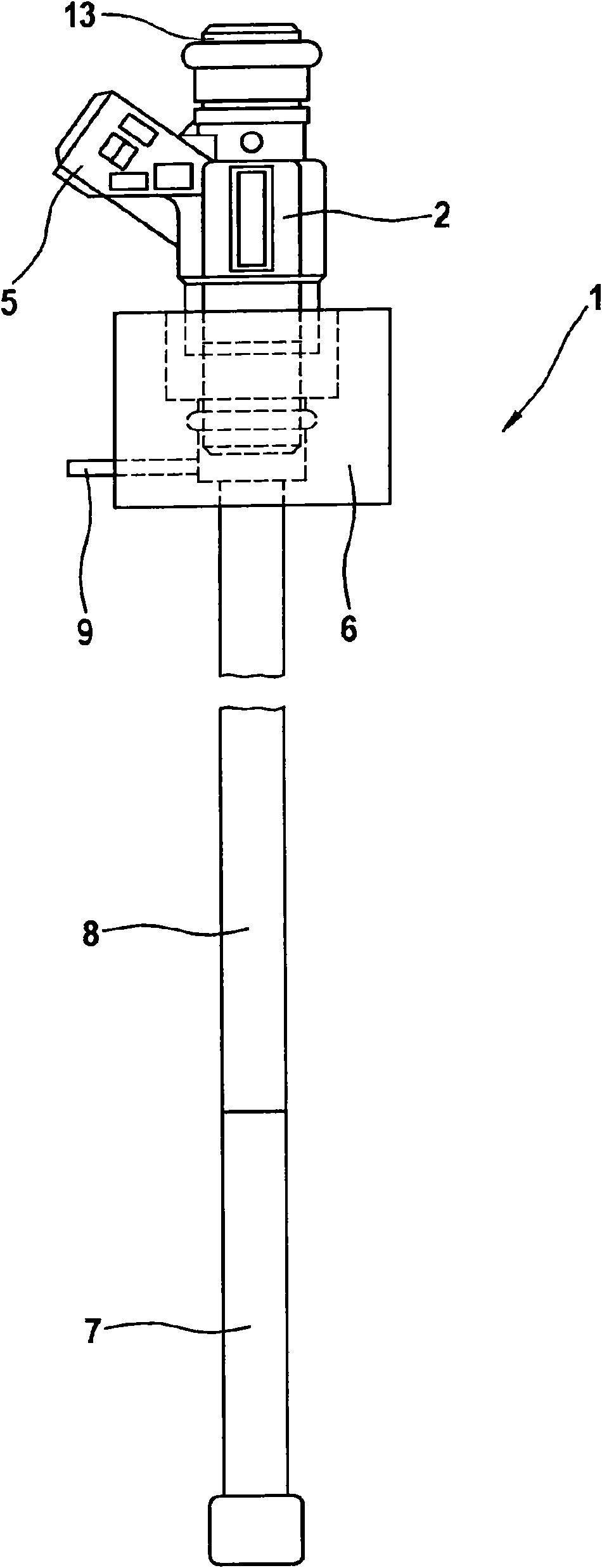
[0021] figure 1 The exemplary embodiment of a metering device 1 according to the invention shown in is implemented in the form of a metering device 1 for a low-pressure fuel injection valve. The metering device 1 is especially suitable for feeding and atomizing fuel or a fuel-gas mixture into a metering chamber (not shown) of a chemical converter (not shown) The reburning device is set to generate heat. Basically, however, such a metering device 1 is particularly suitable for metering fuel in hot surroundings. Known injection valves for the metering of media such as gasoline, diesel fuel, ethanol, methanol, aqueous urea solutions, etc. are designed for ambient temperatures of about 150° C., whereas the metering device 1 according to the invention, in addition to the already described In addition to other applications, it can also be used for exhaust gas aftertreatment or regeneration of particle filters, since in these applications the temperature reaches 700° C., which the ...


PUM


Abstract

The invention relates to a metering device (1) for liquid fuels, in particular for introduction into a chemical reformer for producing hydrogen or into an after-burning apparatus for generating heat. The metering apparatus (1) has at least one proportioning apparatus (2) for proportioning fuel into a proportioning line (8) and a delivery unit (7) which follows the proportioning line (8) and delivers the fuel into a proportioning space. The delivery unit (7) is configured as a purely mechanical valve (11) which opens and closes with a frequency of about 1500 Hz.

Description

technical field [0001] The invention relates to a metering device of the type according to claim 1 . Background technique [0002] In fuel cell-supported transport systems, so-called chemical converters are used to obtain the required hydrogen from hydrocarbon-containing fuels such as petrol, ethanol or methanol, and catalytic burners are used to generate heat especially in the cold start phase and reburning device. [0003] All materials required by the reformer for the reaction process, such as air, water and fuel, are ideally fed into the reaction zone in gaseous form or at least in the form of a mist. Since fuels such as methanol or gasoline and water are present in the transport system in liquid form, they must be prepared just before reaching the reaction zone of the converter. For this purpose, for example, a metering device is required which is able to deliver a corresponding amount of fuel or other substances in a fine atomized form. [0004] The temperatures req...

Claims


Application Information

Patent Timeline
Patent Type & Authority Applications(China)
IPC IPC(8): B01J4/02B01J19/26B05B1/30F02M61/04
CPCC01B2203/1276F02M61/08F02M63/0005C01B2203/1229C01B3/323C01B3/38C01B2203/169F01N3/0253C01B2203/1252C01B2203/1223F01N2610/11B01J4/002F01N2610/1453B01J4/02B01J19/26C01B2203/1247F02M53/043C01B2203/0261
Inventor F·米勒
Owner ROBERT BOSCH GMBH
Why Eureka
Try Eureka