Jet spinning apparatus

A technology of air-flow spinning and air-flow, applied in the field of air-flow spinning devices, which can solve problems such as changes

Active Publication Date: 2009-12-09
SAURER GERMANY GMBH & CO KG
View PDF5 Cites 11 Cited by
  • Summary
  • Abstract
  • Description
  • Claims
  • Application Information

AI Technical Summary

Problems solved by technology

[0005] However, the aforementioned device has the disadvantage that every change that occurs at the air injection nozzle (such as the auxiliary circular air flow) inevitably leads to a change in the suction air flow

Method used


Image

  • Jet spinning apparatus
  • Jet spinning apparatus
  • Jet spinning apparatus

Examples


Embodiment Construction

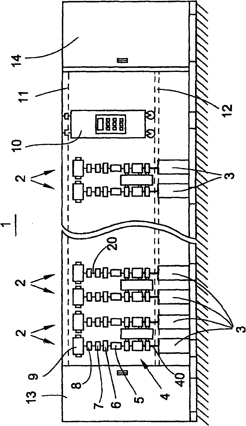
[0031] figure 1 The front view schematically shows a so-called rotor spinning machine 1 . Such a textile machine has a plurality of workstations or spinning stations 2 arranged side by side, which are positioned between so-called machine or end frames 13 , 14 arranged on the end side. as in figure 1 As further shown in , each station 2 is equipped with some feed material, eg slivers 40 stored in the spinning drum 3 . Each spinning station 2 has a drafting device 4 , an air spinning device 5 , a yarn taking-off device 6 , a yarn clearer 7 and a yarn traversing device 8 . The yarn traversing device 8 is responsible for winding the yarn 20 produced from the fiber strands 40 in the open-end spinning device 5 on the winding bobbin 9 in yarn layers that cross each other. Here, the so-called cross-wound bobbins 9 are generally held on a creel (not shown) and driven in rotation by a bobbin drive (also not shown). as in figure 1 As further shown in , the stations 2 of the textile ...


PUM


Abstract

The invention relates to a jet spinning apparatus (5) for producing a thread (20) by means of a circulating airflow, having a hollow spinning cone (19) which is arranged in a spinning housing (15), and having two separate groups of blown air nozzles (25, 30) which can be loaded with compressed air independently of one another, wherein the strength of a vacuum flow which acts on a sliver inlet opening (22) during the spinning process can be set via the arrangement of a first group of blown air nozzles (25) and the strength of an airflow which circulates in the region of the spinning cone (19) can be predefined via the arrangement of a second group of blown air nozzles (30). There is provision according to the invention for the blown air nozzles (25) of the first group to be arranged offset at a spacing (b) with regard to the longitudinal centre axis (24) of the jet spinning apparatus (5), with the result that an airflow can be introduced into the jet spinning apparatus (5) via the blown air nozzles (25) during the spinning process, which airflow has a tangential blown air component in order to assist the airflow which circulates in the region of the spinning cone (19).

Description

technical field [0001] The present invention relates to an open-end spinning device for producing yarn by means of a circulating air flow according to the preamble of claim 1 . Background technique [0002] Open-end spinning devices for the manufacture of textile yarns are known and described in greater detail in numerous patent applications. [0003] For example, DE 40 36 119 C2 describes an air-jet spinning device which essentially comprises a spinneret assembly arranged on the input side and a rotatably mounted hollow spinning spindle. In this case, in addition to the gas injection nozzles for generating the circulating air flow, the spinneret assembly has a fiber strand guide, which for the fed fiber strand corresponds to a twist stop. The circulating air flow induced by the gas injection nozzles in the area of ​​the fiber input openings of the spinneret pack results in a suction air flow which facilitates feeding the fiber strands drawn in the upstream drafting device ...

Claims


Application Information

Patent Timeline
Patent Type & Authority Applications(China)
IPC IPC(8): D01H1/115D01H4/02
CPCD01H1/115D01H4/02
Inventor 弗兰切塞·卡诺·卡萨斯何塞-安东尼奥·托内罗-加尔恰托马斯·魏德何塞-安东尼奥·托内罗-加尔恰
Owner SAURER GERMANY GMBH & CO KG
Why Eureka
Try Eureka