
Method for operating a textile machine which is provided with a vacuum device and produces crosswound bobbins

A textile machine and negative pressure technology, which is applied in the field of manufacturing cross-winding bobbins, can solve the problems of unavailable, difficult textile machines, etc.

Active Publication Date: 2009-12-09
SAURER GERMANY GMBH & CO KG
View PDF3 Cites 3 Cited by
  • Summary
  • Abstract
  • Description
  • Claims
  • Application Information

AI Technical Summary

Problems solved by technology

[0009] Although the open-end rotor spinning machine is also equipped with a suction device (in this suction device, the speed of the drive motor of the suction group can be increased up to the maximum speed in order to increase the negative pressure level if necessary), but if the suction of the spinning machine If the air demand exceeds the maximum suction supply of the relevant suction device, it brings considerable difficulties to this known weaving machine.
That is to say, in this case there is a big problem, that is, the suction system of the textile machine cannot provide enough vacuum for all the work requiring additional vacuum, although the drive motor of the suction unit is already running at maximum speed. supply the necessary suction air at the same time

Method used


Image

  • Method for operating a textile machine which is provided with a vacuum device and produces crosswound bobbins

Examples


Embodiment Construction

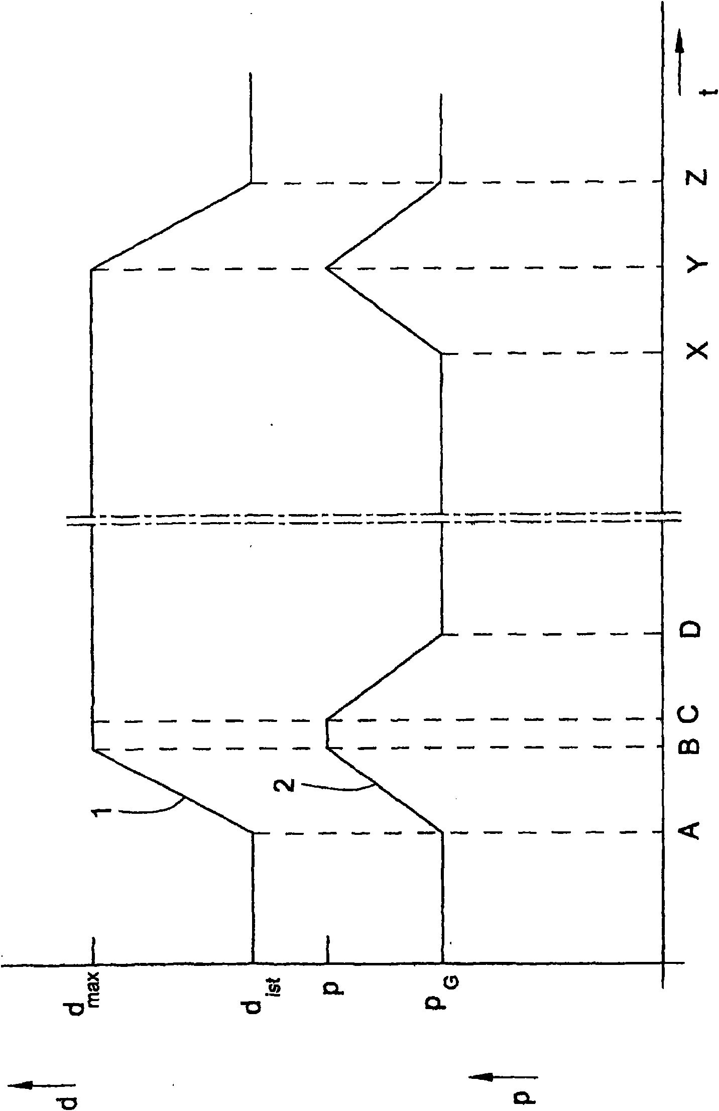
[0021] In the drawing, the rotational speed curve schematically represented by the passage curve 1 of the drive motor of the suction unit of the textile machine is shown graphically, and the passage curve 2 in the suction unit of the textile machine when the textile machine is restarted after a batch change Schematic representation of the negative pressure curve. In this case, the abscissa represents the time course of the method according to the invention, with A, B, C, etc. marking different points in time which will be described further below. The ordinate shows the negative pressure level p present in the textile machine suction system and the rotational speed level d of the drive motor of the textile machine suction unit.

[0022] When the open-end spinning machine is started up again after a batch change, a predeterminable negative pressure p first occurs in the suction device of the textile machine G , the negative pressure is specified in such a way that it satisfies ...


PUM


Abstract

The invention relates to a method for optimizing the number of workstations, which can be supplied with additional vacuum simultaneously on account of circuits, of a textile machine which has a multiplicity of workstations, wherein the textile machine has a vacuum system with at least one vacuum assembly, the vacuum output of which can be increased via the rotational speed of its drive motor, regulated by monitoring of the vacuum level, until a maximum rotational speed is reached. There is provision according to the invention for a value for a rotational speed reserve to be calculated from the known maximum rotational speed of the drive motor of the vacuum assembly, which maximum rotational speed defines the maximum vacuum output of the vacuum system of the textile machine, and from a prevailing actual rotational speed of the drive motor of the vacuum assembly, which actual rotational speed results from the current vacuum requirement of the textile machine, using which value for a rotational speed reserve the number of workstations is determined which can still be supplied with additional vacuum. A maximum number of workstations which can be supplied simultaneously with additional vacuum is determined from this number, increased by the number of workstations which are currently already being supplied with additional vacuum on the basis of the actual rotational speed of the drive motor, and vacuum requirements are rejected which exceed this maximum number of circuits.

Description

technical field [0001] The invention relates to a method according to the preamble of the first aspect of the invention, aimed at optimizing the number of workstations of a textile machine having a plurality of workstations which can be simultaneously supplied with an additional negative pressure And for the manufacture of cross-wound bobbins. Background technique [0002] In the case of textile machines for producing cross-wound bobbins with several stations, such as automatic cross-winders or open-end rotor spinning machines, it has been known that during their operation it is necessary to continuously contribute to the work of such textile machines. bit to supply suction air to function properly. [0003] For example, suction air is always required at the stations of automatic cross-winders for bobbin dust removal, that is to say a device is required during the rewinding process, which is responsible for cleaning the of dirt and dust. In addition, these stations have y...

Claims


Application Information

Patent Timeline
IPC IPC(8): D01H13/00
CPCD01H4/06D01H13/1691D01H13/00B65H2701/31B65H54/707D01H5/66D01H1/115
Inventor 博多·汉森
Owner SAURER GERMANY GMBH & CO KG
Learn More