Insulating device and tensioning device for a high temperature fuel cell system component

A technology for high temperature fuel cells and system components, which is applied in the field of devices and can solve problems such as cracks in thermal insulation materials

Inactive Publication Date: 2009-12-09
EHNERDEJ GMBKH
View PDF1 Cites 5 Cited by
  • Summary
  • Abstract
  • Description
  • Claims
  • Application Information

AI Technical Summary

Problems solved by technology

Because the shrinkage of the insulation material can cause cracks to appear
This problem can also be acute if several components of the fuel cell system are co-located in so-called thermal barriers

Method used


Image

  • Insulating device and tensioning device for a high temperature fuel cell system component
  • Insulating device and tensioning device for a high temperature fuel cell system component

Examples


Embodiment Construction

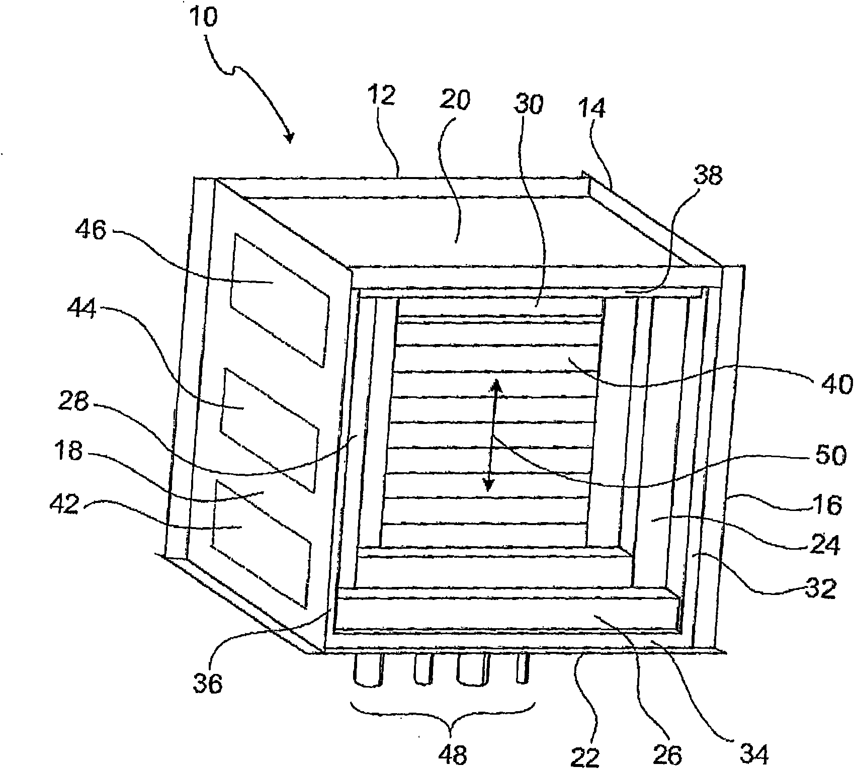
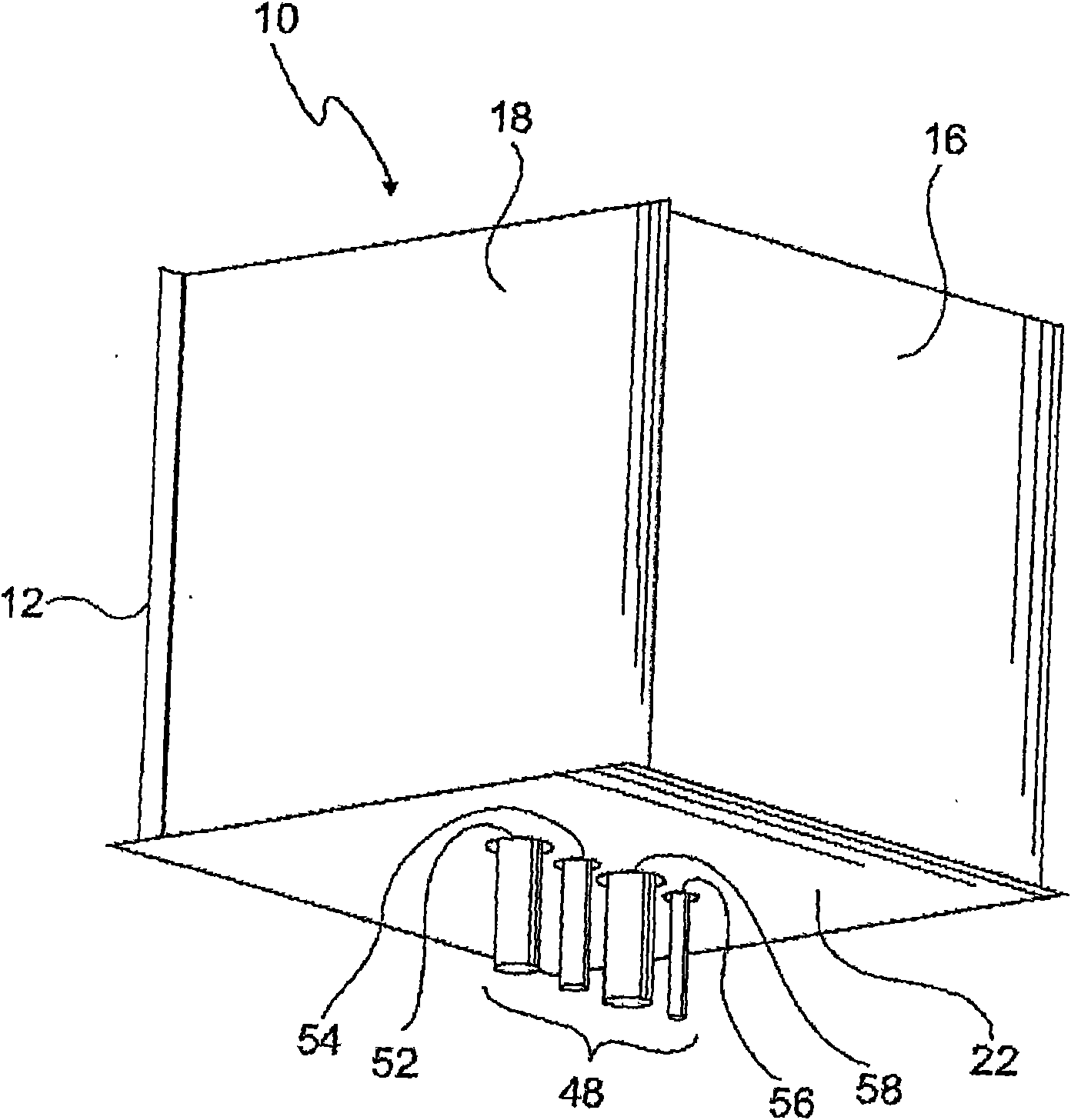
[0019] exist figure 1 The device 10 shown in FIG. 2 includes an insulated container in which at least one high temperature fuel cell system component is disposed. The vessel comprises a vessel shell formed from six mutually welded plates 12-22. The front panel 16 is shown partially cut away to allow a view of the internal structure of the device 10 . Inside the container housing 12 - 22 is arranged a high-temperature fuel cell stack 40 , the stack direction of which simultaneously also represents the preferred expansion direction 50 . The high temperature fuel cell stack 40 is connected to supply lines 48 which include, inter alia, an anode gas input and output and a cathode gas input and output. The supply lines 48 are led outwardly through the perforations 52 - 58 in the base plate 22 . The apparatus 10 may also house a reformer 42 and / or a combustor 44 and / or a controller 46, as shown by corresponding dashed boxes. The high temperature fuel cell stack 40 is surrounded b...


PUM

PropertyMeasurementUnit
densityaaaaaaaaaa

Abstract

The invention relates to a device (10) comprising a thermally insulating container (12-38) and at least one high temperature fuel cell system component (40) that is arranged in the container (12-38), said high temperature fuel cell component being surrounded by at least one insulating layer (24-30) made of a first material. A tensioning device acts upon the insulating layer. According to the invention, the tensioning device comprises one or more plate-type elements (32 -38) that are made of a second material and that act upon the insulating layer and that are supported on the container housing (12-22). Said elements can be elastically deformed when a pressure is applied, at which the first material cannot be deformed.

Description

technical field [0001] The invention relates to a device comprising a heat-insulated container and at least one component of a high-temperature fuel cell system arranged in the container, which is surrounded by at least one heat-insulating layer of a first material, wherein a hold-down device acts on on the insulation. Background technique [0002] The production of fuel cell stacks with a defined compaction is known, for example, in connection with SOFC fuel cell systems. The compression used in the prescribed system during production, storage and installation of the fuel cell stack can in particular be a temporary compression which can be removed after the final compression has been set. The final pressing can be effected, for example, as described in DE 103 08 382 B3. According to the teaching of this patent document, the final compression is provided in the form of clamping frames and tension rods on the outside of the thermal insulation surrounding the high-temperatur...

Claims


Application Information

Patent Timeline
Patent Type & Authority Applications(China)
IPC IPC(8): H01M8/24H01M8/12
CPCH01M8/2475H01M8/248Y02E60/50Y02E60/525H01M2008/1293
Inventor 延斯·哈佛麦斯特马蒂亚斯·波尔策
Owner EHNERDEJ GMBKH
Why Eureka
Try Eureka