
Camera module, and imaging device

A camera module and imaging optical system technology, which is applied in the field of camera modules and imaging devices, can solve the problems of plasticity reduction, application, and large stress of flexible substrates, and achieve the effect of shortening the protruding length

Inactive Publication Date: 2009-12-09
SONY GRP CORP
View PDF1 Cites 8 Cited by
  • Summary
  • Abstract
  • Description
  • Claims
  • Application Information

AI Technical Summary

Problems solved by technology

[0005] However, when the length of the flexible substrate is shortened, the plasticity of the flexible substrate in the direction along its surface decreases
Therefore, when the printed wiring board is fixed to the lens barrel by screwing, there is a concern that the connector that engages the flexible board and the printed wiring board with each other may be damaged depending on fluctuations in the mounting positions of the printed wiring board and the flexible board. or apply large stress to the soldered portion of the connector

Method used


Image

  • Camera module, and imaging device
  • Camera module, and imaging device
  • Camera module, and imaging device

Examples


Embodiment Construction

[0019] Embodiments of the present invention will be described below with reference to the drawings.

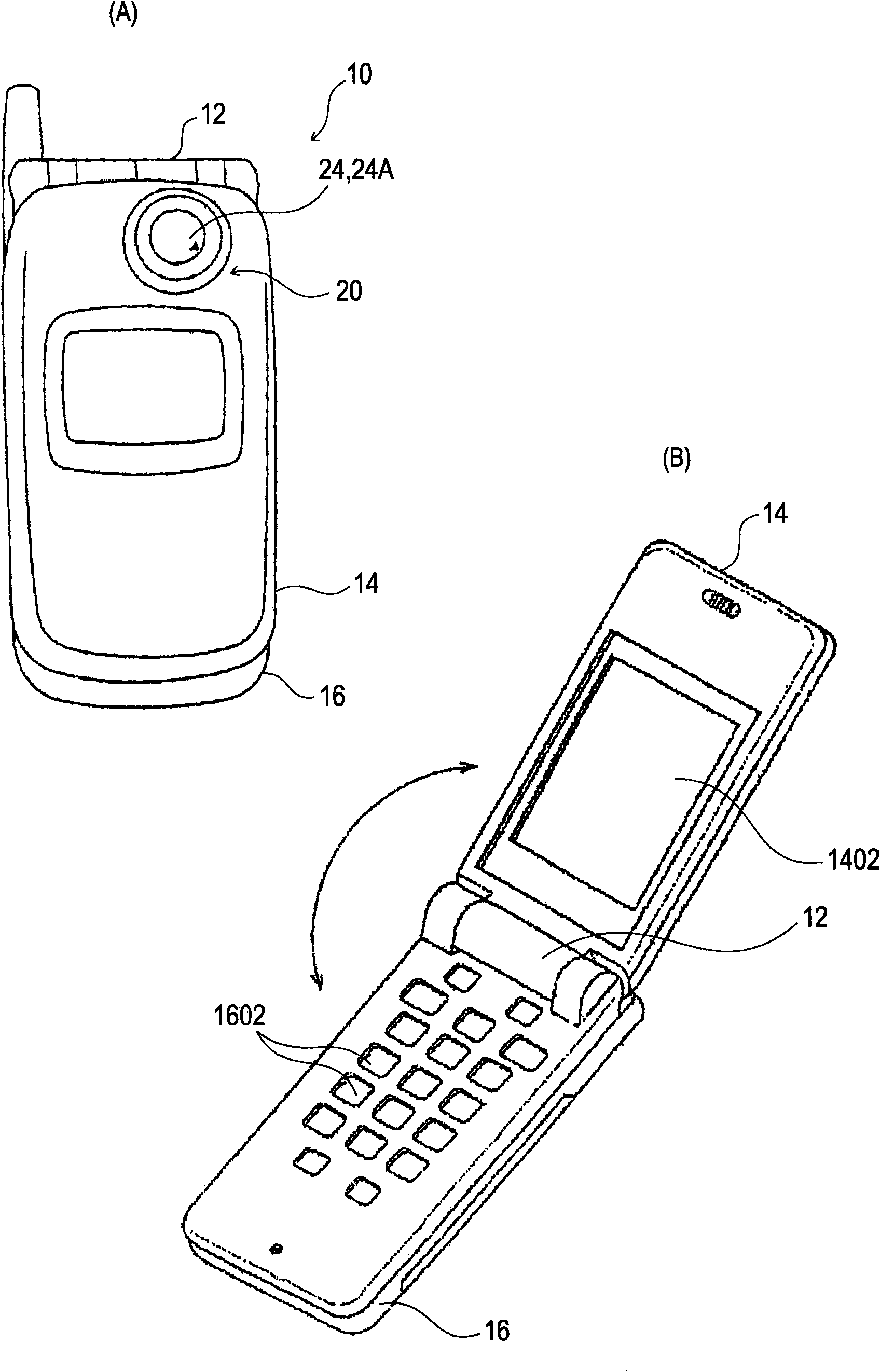
[0020] figure 1 (A) and (B) are external views showing an example of an imaging device equipped with the camera module 20 of this embodiment.

[0021] Such as figure 1 As shown, the imaging device 10 is a portable cellular phone, and has a first housing 14 and a second housing 16 coupled to each other so as to be pivotable on a hinge portion 12 .

[0022] A liquid crystal display panel 1402 is provided on the inner surface of the first housing 14 , and operation switches 1602 including tenkeys and function keys are provided on the inner surface of the second housing 16 .

[0023] The camera module 20 is mounted on a proximal portion of the first housing 14 . Images picked up by the camera module 20 are displayed on the liquid crystal display panel 1402 .

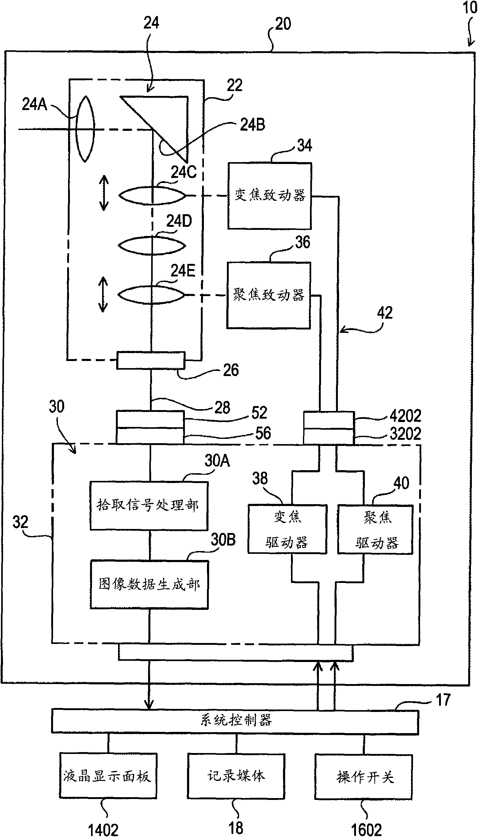
[0024] figure 2 is a block diagram showing the configuration of the imaging device 10 .

[0025] The imaging device...


PUM


Abstract

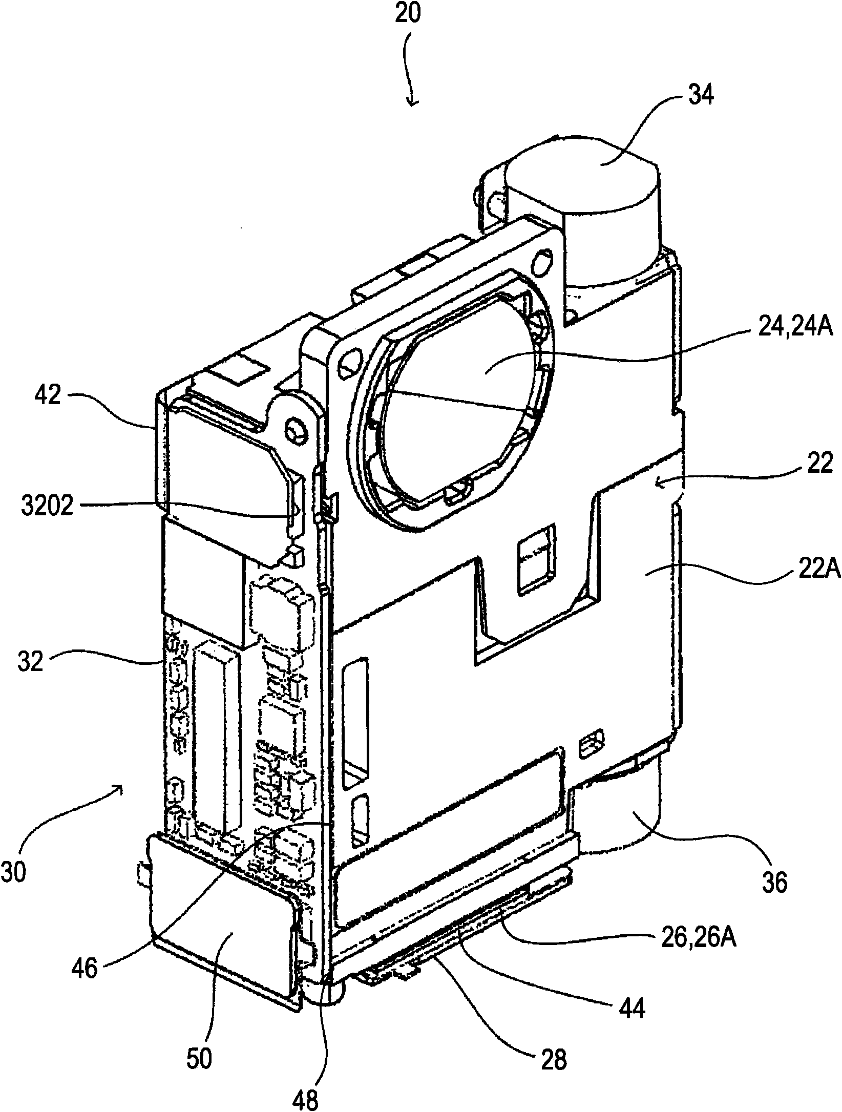
Disclosed are a camera module, which is advantageous for relaxing the stress to be applied to a connector or a flexible substrate when a printed circuit board is mounted, and an electronic device. A lens mount (22) has a first side face (44) and a second side face (46) intersecting each other. An imaging element (26) is mounted to have its back face (26A) directed to a flexible substrate (28). A signal processing unit (30) is mounted on a rigid printed circuit board (32). The flexible substrate (28) has a protruding portion (50) protruding from an intersecting portion (48), at which the first side face (44) and the second side face (46) intersect. The printed circuit board (32) is arranged on the second side face (46) through a tack mechanism (54), and the protruding portion (50) of the flexible substrate (28) is folded at the intersecting portion (48) so that a flexible substrate side connector (52) is joined to a printed circuit board side connector (56) and so that an adhesive layer (58) is adhered to the second side face (46). Thus, the flexible substrate (28) and the printed circuit board (32) are arranged in the lens mount (22).

Description

technical field [0001] The present invention relates to a camera module and an imaging device. Background technique [0002] In the past, there have been proposed camera modules that include a lens barrel equipped with an imaging optical system that picks up an object image introduced by the imaging optical system, an image sensor, and a signal processing unit. , the signal processing unit performs predetermined signal processing on the pickup signal supplied from the image sensor (refer to JP-A-2000-207497). [0003] In this camera module, presumably, the signal processing unit is formed in a rigid printed wiring substrate, the printed wiring substrate is mounted to the side of the lens barrel, and the pickup signal sent from the image sensor is guided to the printed wiring substrate via the flexible substrate. substrate. In this case, the connection between the flexible board and the printed wiring board is realized by a connector. [0004] By the way, the pickup signal...

Claims


Application Information

Patent Timeline
Patent Type & Authority Applications(China)
IPC IPC(8): H04N5/335H04N5/225
CPCH05K1/147H04N5/2257H04N5/2251G03B17/02H04N23/55H04N23/57H04N23/00H04N25/00
Inventor 中山武彦
Owner SONY GRP CORP
Learn More