Thrust generating apparatus

A technology for generating devices and thrust, applied in ship propulsion, propulsion components, transportation and packaging, etc., can solve the problems of complicated mechanism, increased hull resistance, inflow of other objects, etc., and achieve the effect of high-efficiency steering and simple structure

Inactive Publication Date: 2009-12-16
长山明
View PDF1 Cites 6 Cited by
  • Summary
  • Abstract
  • Description
  • Claims
  • Application Information

AI Technical Summary

Problems solved by technology

[0010] However, due to the overall size of the device, the complexity of the shaft system for rotating the propeller, and constraints on the ship's interior layout, the side thrusters had to be installed close to the parallel parts of the hull, and the length of the pipe to be longer than necessary, resulting in a drop in thrust
Therefore, if the opening position of the inlet and outlet of the ducts of the lateral thrusters is moved to the front of the waterline with an angle of incidence, the resistance of the hull will increase, and it will also lead to the inflow of other objects
Therefore, if protective devices are installed at the openings at both ends of the entrance and

Method used


Image

  • Thrust generating apparatus
  • Thrust generating apparatus
  • Thrust generating apparatus

Examples


Embodiment Construction

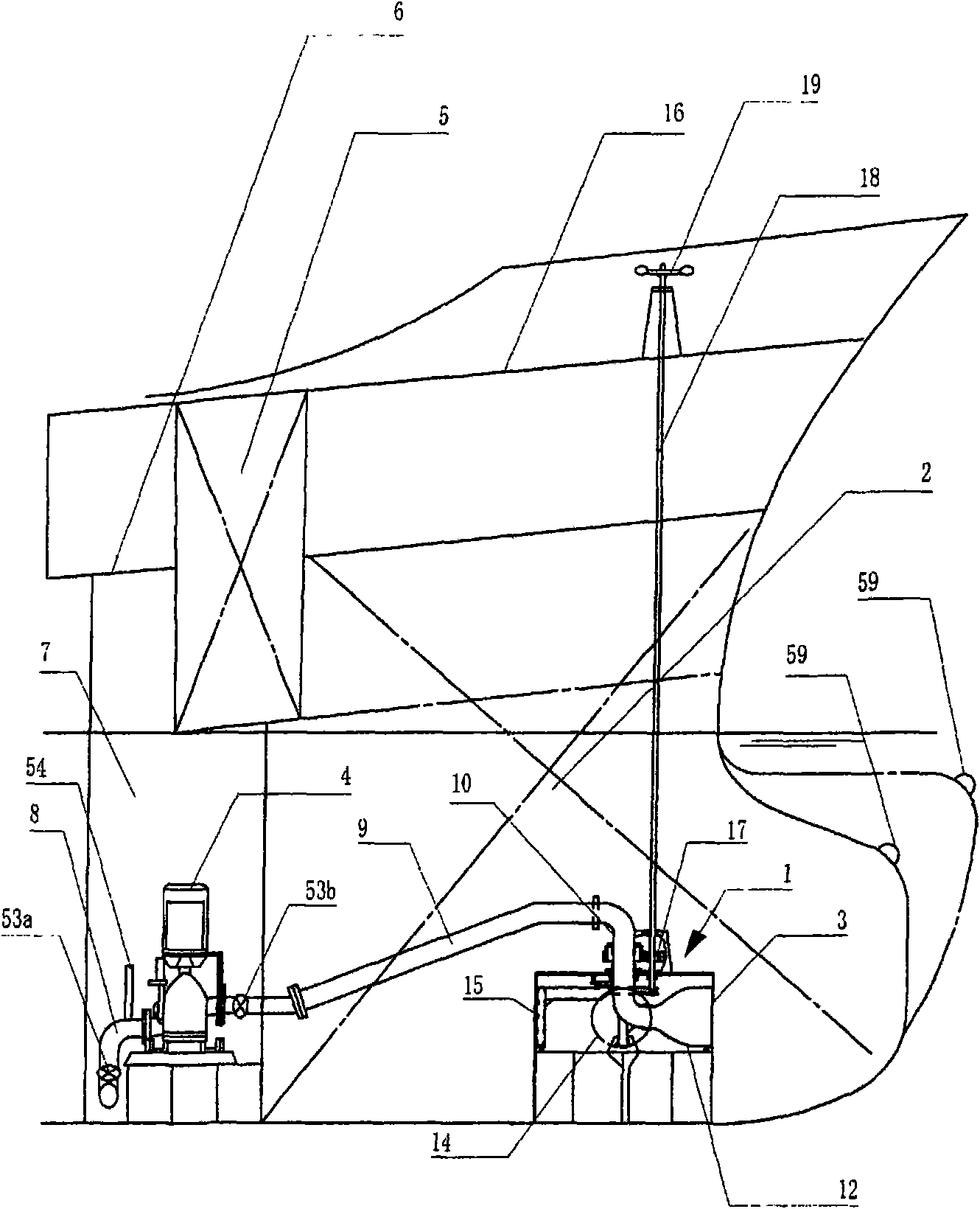
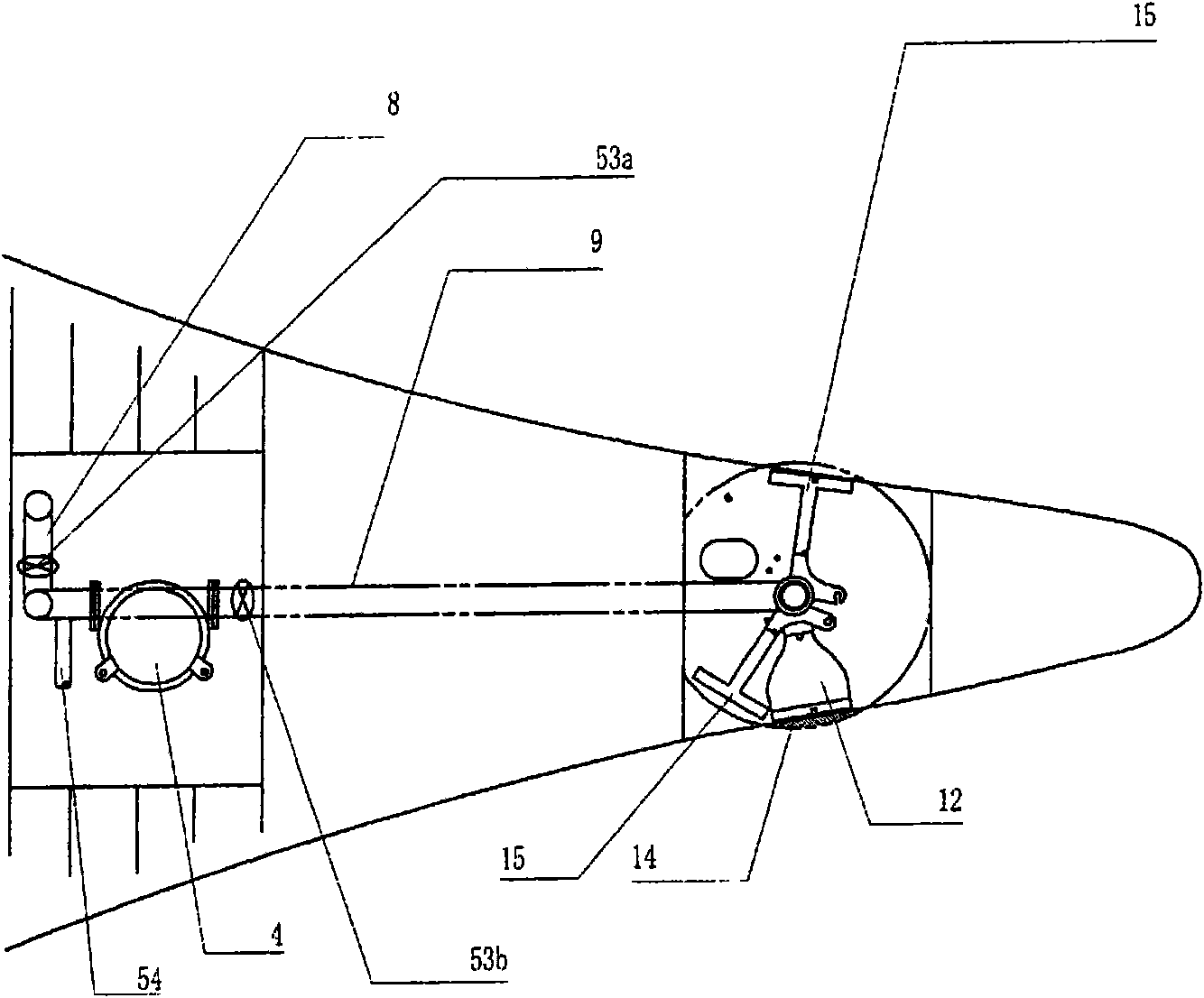
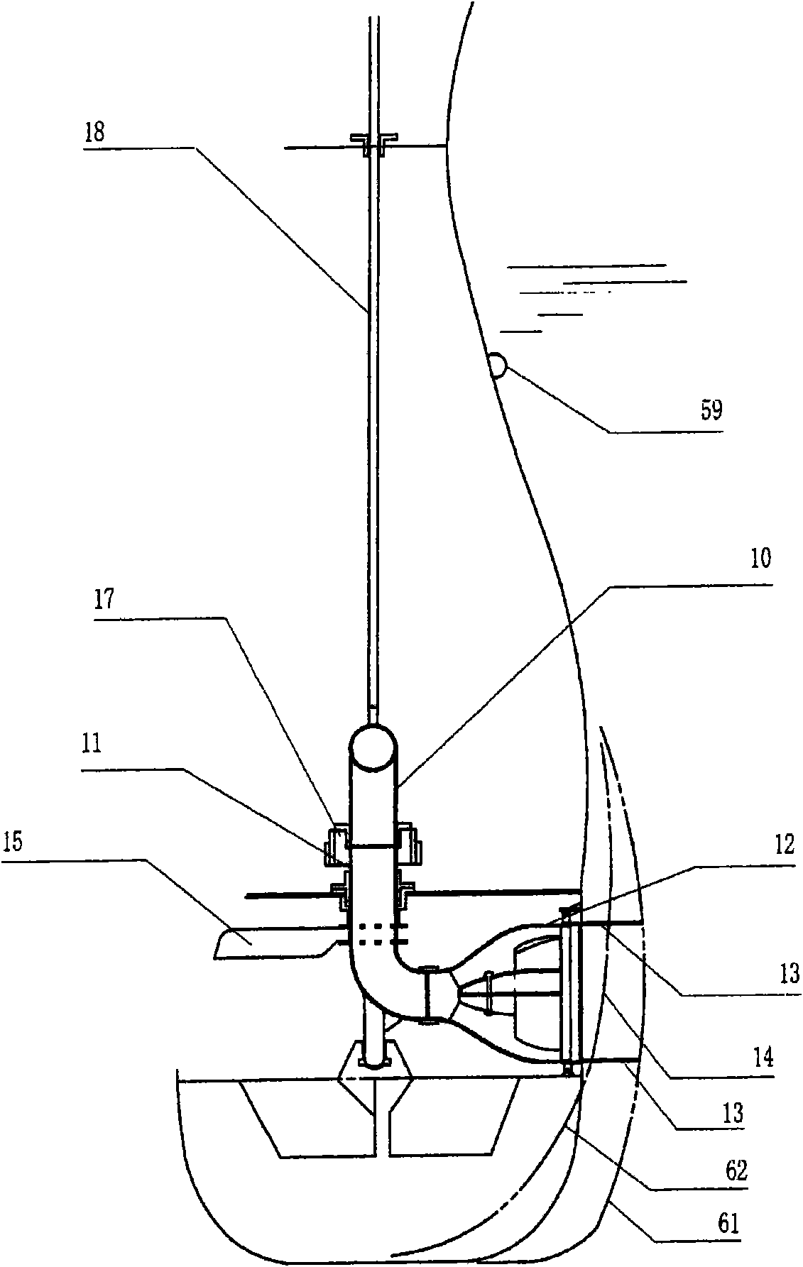
[0066] Next, the configuration of the present invention will be described in detail with reference to the following figures.

[0067] figure 1 It is a longitudinal sectional view of the bow of the device installed with the present invention; figure 2 is a plan view of the floor surface on which the device is installed; image 3 is a cross-sectional view of the location of the device at the end of the bow; Figure 4 is a longitudinal sectional view of the nozzle of the thrust generating device of the device; Figure 5 is a front view showing the structure of the nozzle; Figure 6 , Figure 7 and Figure 8 It is a plan view showing the operating positions of the nozzles and revolving doors in the thrust generator chamber; Figure 9 and Figure 10 is a detailed drawing of the revolving center of the revolving door; Figure 11 yes Figure 6 A-A direction view; Figure 12 yes Figure 11 C-C direction view; Figure 13 yes Figure 11 D-D direction view; Figure 14 yes...


PUM


Abstract

A thrust generating apparatus is provided that can transform a spouting water flow having a small diameter into a water flow having a large diameter, and that can be provided at the bow or the stern end. A bell-shaped nozzle is coupled to an ejection port of a pump water flow, a ring having a blade-shaped cross section is disposed inside the nozzle, and a shell-shaped cone is disposed inside the ring on the center line of a water flow. Thereby, an ejection flow is straightened, and a thrust is generated. In addition, the bottom of the cone is open, a slit is further provided at a shoulder portion of the cone forward of the ring, and the water flow inside the cone is in communication with a water flow outside the cone. Furthermore, a rotating door is provided that enables the nozzle to pivot toward a shell plating opening on a port side or a starboard side, and that closes or opens the shell plating opening in accordance with the position of the nozzle.

Description

technical field [0001] The present invention relates to a thrust generating device of a lateral thruster which can be arranged at the bow end or stern end of a displacement ship, and a revolving door which automatically opens and closes an opening of an outer plate in conjunction with it. Background technique [0002] A lateral propeller is a device installed at the bow or stern of a ship to move the ship laterally. Most of the lateral thrusters are installed in large ships, especially ships such as ferries with many offshore berthing times. Smaller boats, on the other hand, are less likely to have side thrusters because they are relatively easy to maneuver, or move the boat with little effort. [0003] However, with the shortage of manpower and the aging of the crew in recent years, the demand for the function of using side thrusters in small ships has also increased. Therefore, Japanese Patent Application Laid-Open No. 5-16594 proposes a side thruster that jets seawater ...

Claims


Application Information

Patent Timeline
IPC IPC(8): B63H25/42B63H11/02
CPCB63H11/107B63H11/103B63H11/10B63H11/02B63H25/42
Inventor 长山明
Owner 长山明
Why Eureka
Try Eureka