Scroll compressor

A scroll compressor, scroll technology, applied in the field of scroll compressors, to achieve the effect of eliminating bad phenomena

Inactive Publication Date: 2009-12-16
SANYO ELECTRIC CO LTD
View PDF1 Cites 0 Cited by
  • Summary
  • Abstract
  • Description
  • Claims
  • Application Information

AI Technical Summary

Problems solved by technology

[0006] The present invention is made to solve the above-mentioned problems in the prior art, and its object is to provide a scroll comp

Method used


Image

  • Scroll compressor
  • Scroll compressor

Examples


Embodiment 1

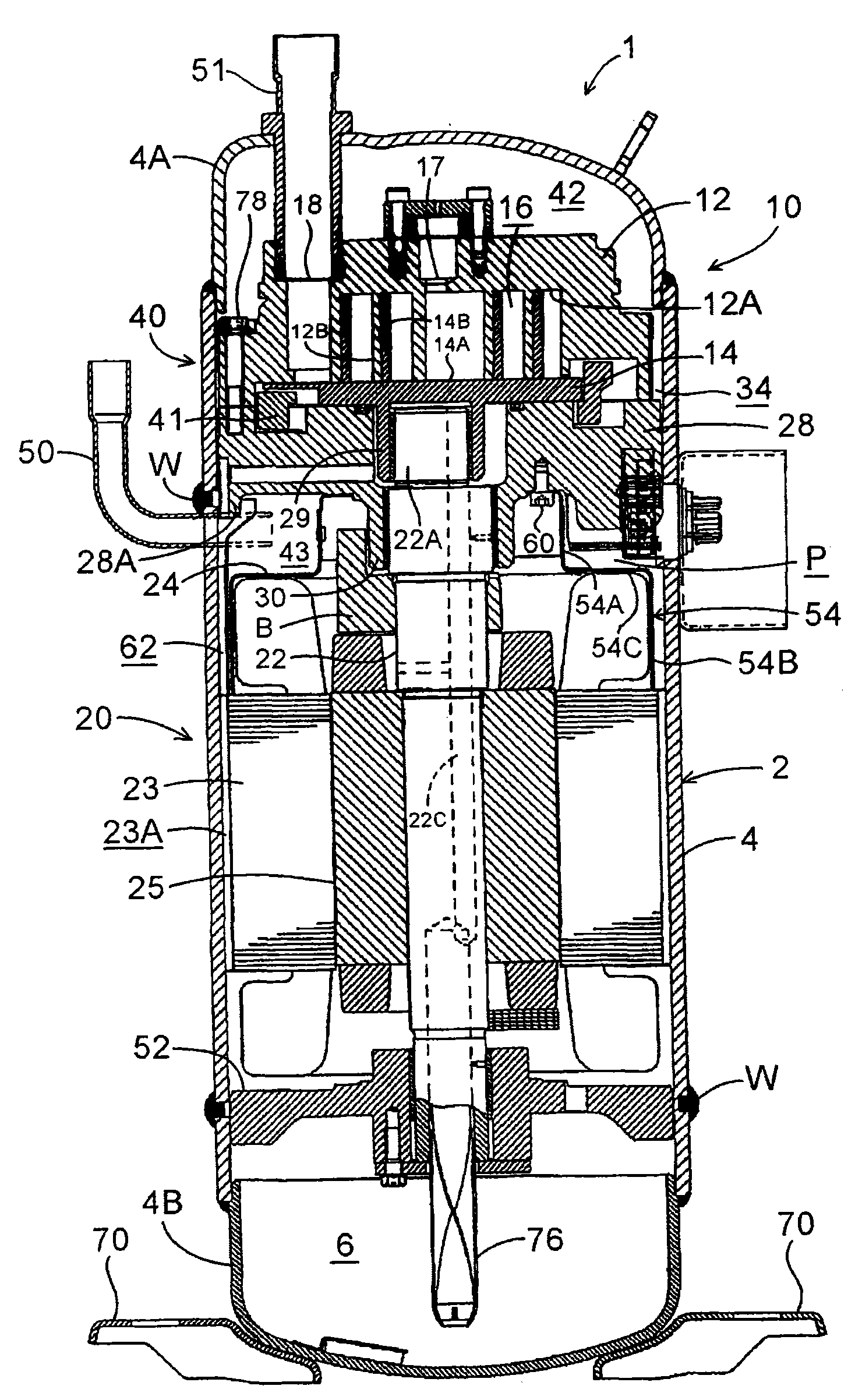
[0042] Hereinafter, embodiments of the present invention will be described in detail with reference to the drawings. figure 1 It is a longitudinal sectional side view of an internal high-pressure type scroll compressor 1 having a scroll compression unit 10 showing an embodiment of the present invention.

[0043] The scroll compressor 1 in this embodiment belongs to the internal high pressure type, such as figure 1 As shown, its structure includes: an elongated cylindrical airtight container 2 made of steel plates, an electric assembly 20 (electric motor) arranged and accommodated in the inner space of the airtight container 2 , and an upper side of the electric assembly 20 The scroll compression assembly 10 is driven by the rotating shaft 22 of the electric assembly 20 . The structure of the airtight container 2 includes: a container body 4 for accommodating the electric assembly 20 and the scroll compression assembly 10, a bowl-shaped end cap 4A installed for closing the upp...

Embodiment 2

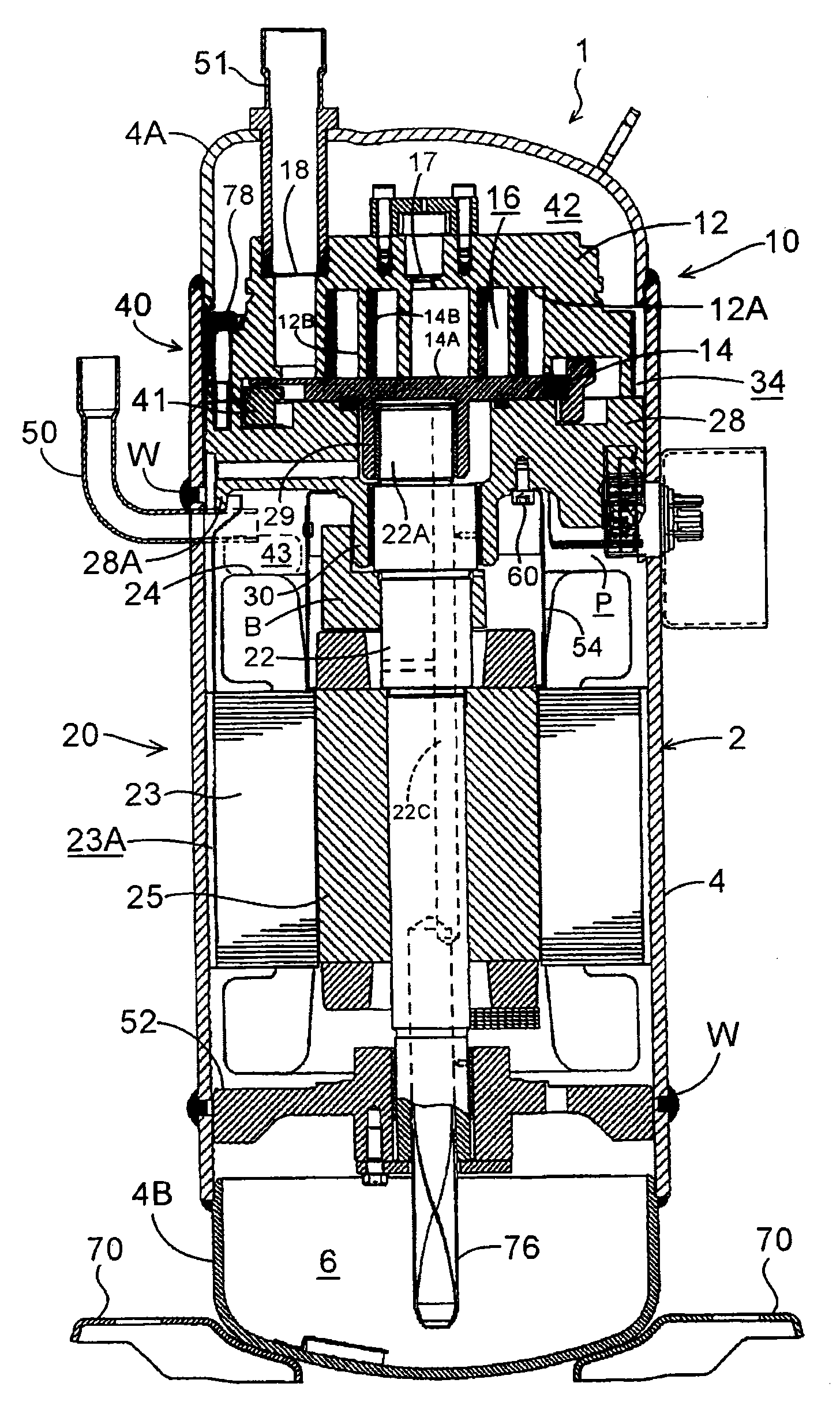
[0069] exist figure 2 A scroll compressor 1 according to another embodiment of the present invention is shown in FIG. This scroll compressor 1 has substantially the same structure as the above-mentioned embodiment. Next, the different parts will be described. In addition, the same code|symbol is attached|subjected to the same part as the above-mentioned embodiment, and the description is abbreviate|omitted. That is, if figure 2 As shown, the scroll compressor 1 is formed by changing the shape of the shielding plate 54 described in the foregoing embodiments.

[0070] The shielding plate 54 is provided outside the bearing portion 30 at a predetermined interval, and the lower edge of the shielding plate 54 extends to the stator 23 located slightly below the upper surface of the coil end 24 on the rotor 25 side. near the upper end of the stator coil and abut against the stator core. That is, the shielding plate 54 is arranged inside the coil end 24 of the stator 23, between...


PUM


Abstract

The present invention relates to a scroll compressor effectively solving trouble in which oil flowing out from a bearing part is discharged from a discharge pipe. A shield plate 54 is provided which leads from a support frame (an upper support frame 28) to a stator 23 of a motor element 20, and surrounds the periphery of a bearing portion 30. The shield plate 54 partitions a space between the support frame 28 (the upper support frame 28) and the motor element 20, into the inner side on which a rotor 25 of the motor element 20 is located and the outer side on which a discharge pipe 50 is located.

Description

technical field [0001] The invention relates to a scroll compressor, which accommodates an electric assembly and a scroll compression assembly driven by the electric assembly in a vertically long airtight container, and the scroll compression assembly compresses the refrigerant sucked by the suction pipe It is discharged from a discharge pipe, the suction pipe is installed on the end cap constituting the airtight container, and the discharge pipe is installed on the container body constituting the airtight container. Background technique [0002] At present, such a scroll compression mechanism is such that an electric motor (an electric assembly composed of an electric motor) and a scroll compression assembly driven by the electric motor are accommodated in a vertically long airtight container, and the scroll compression assembly is used to suck water from the suction pipe. The refrigerant gas is compressed, and the suction pipe is installed on the end cap that constitutes t...

Claims


Application Information

Patent Timeline
IPC IPC(8): F04C18/02F04C29/00
Inventor 饭塚敏坂本泰生小池良明杉本和禧
Owner SANYO ELECTRIC CO LTD
Why Eureka
Try Eureka