Material loading trolley moving mechanism of electronic product annealing or sintering furnace

A technology of electronic products and moving mechanism, which is applied in the field of moving mechanism of loading trolley, which can solve the problems of complete vehicle product scrapping, large cumulative error, and large gear wear, and achieve the effect of avoiding out-of-synchronization and ensuring the moving distance

Inactive Publication Date: 2009-12-16
SUZHOU HUIKE EQUIP CO LTD
View PDF0 Cites 3 Cited by
  • Summary
  • Abstract
  • Description
  • Claims
  • Application Information

AI Technical Summary

Problems solved by technology

However, in the actual use process, the effect of synchronous movement between the loading trolleys is not ideal, because it is difficult for the motors on each loading trolley to work at the same time when starting, and there is often an amount of advance or lag. The greater the number, the greater the cumulative error; in addition, the wear degree of the gear and the rack will be different, for example, some gears on the loading trolley wear more, while others do not, resulting in load The trolley cannot move in step
Due to the above two factors, it often happens that the same loading trolley rides across two areas, that is, two different temperature zones, which has a serious impact on the annealing or firing quality of electronic products, and even makes the entire vehicle product scrapped.
[0003] With the gradual popularization of flat-panel TVs, the annealing or firing requirements for plasma display (PDP) glass substrates are more stringent. If the loading trolley cannot run synchronously, it cannot adapt to the annealing or firing of glass substrates

Method used


Image

  • Material loading trolley moving mechanism of electronic product annealing or sintering furnace
  • Material loading trolley moving mechanism of electronic product annealing or sintering furnace

Examples


Embodiment Construction

[0018] In order to enable the examiners of the patent office, especially the public, to understand the technical essence and beneficial effects of the present invention more clearly, the applicant will describe in detail below in conjunction with the accompanying drawings in the form of embodiments, but none of the descriptions of the embodiments is a description of the present invention. Restriction of the inventive solution, any equivalent transformation made according to the concept of the present invention which is only in form but not in substance shall be regarded as the scope of the technical solution of the present invention.

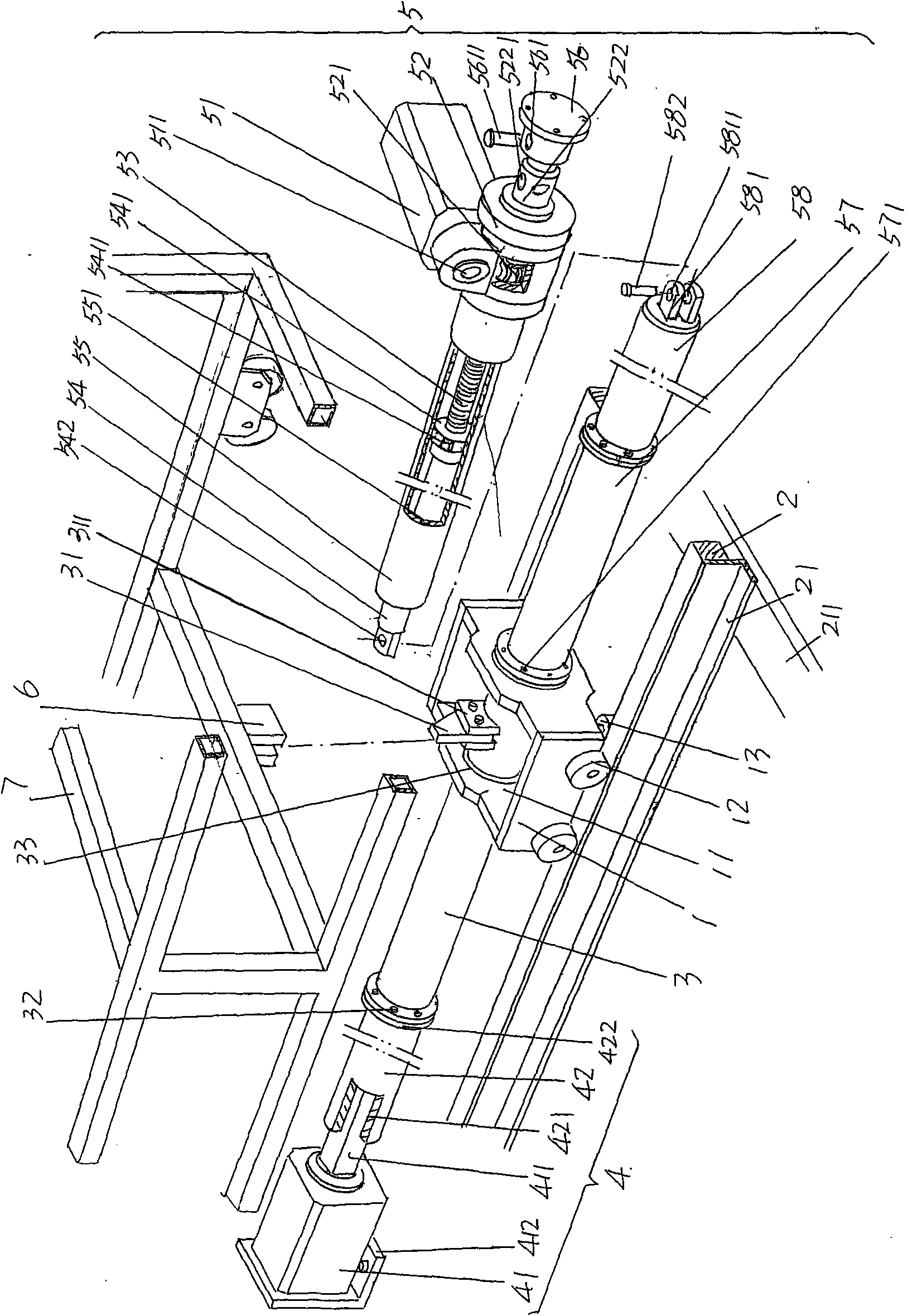
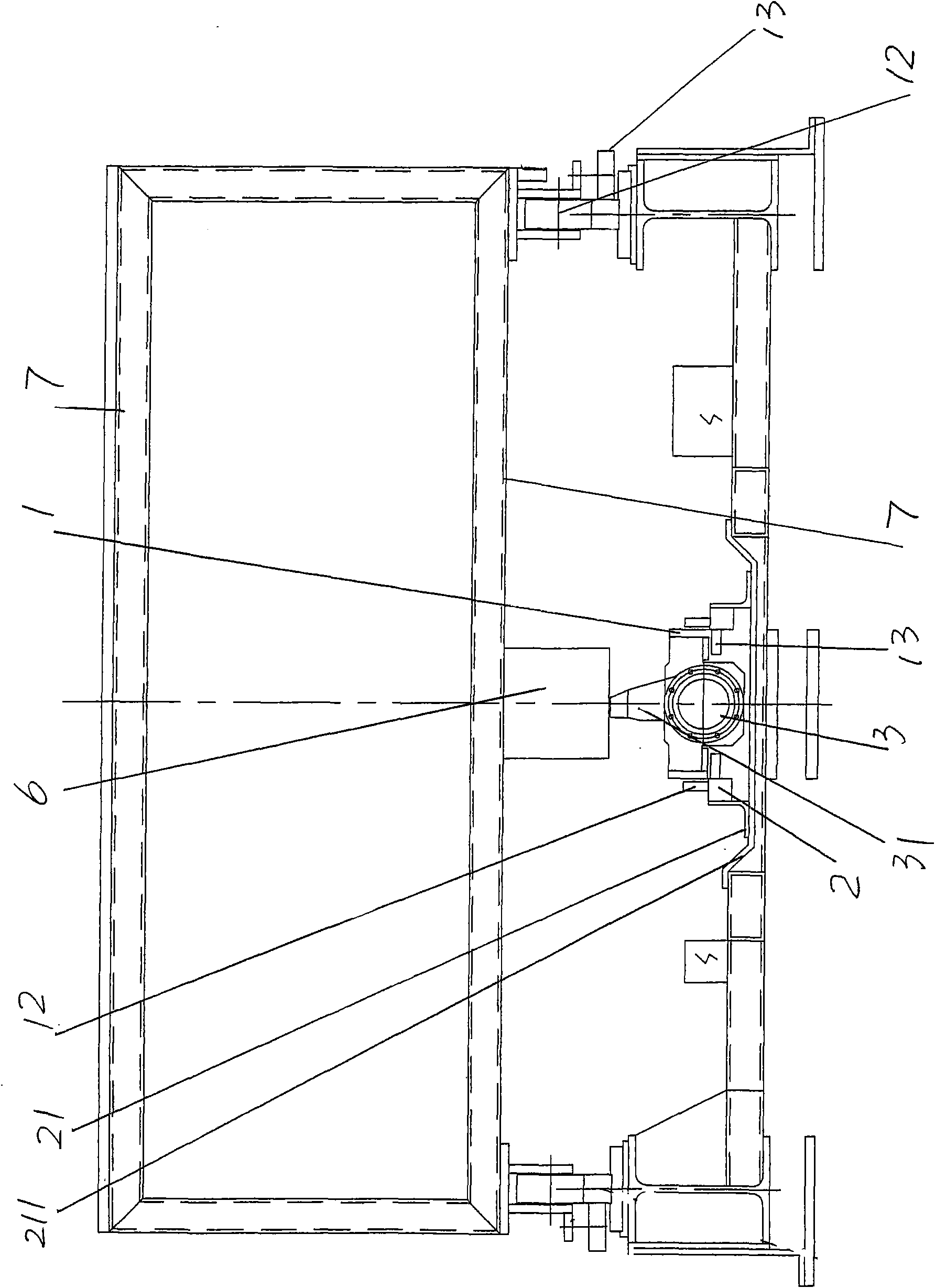
[0019] please see figure 1 and figure 2 , provides an embodiment of the moving mechanism of the loading trolley of the annealing or firing furnace for electronic products of the present invention. It is movably fitted on a pair of guide rails 2 laid parallel to each other. In order to prevent the moving seat 1 from derailing, a pair of roller...


PUM


Abstract

The invention discloses a material loading trolley moving mechanism of an electronic product annealing or sintering furnace, and belongs to the technical field of industrial stoves. The material loading trolley moving mechanism comprises a moving seat, a sliding sleeve, a sliding sleeve rotating device, a moving seat driving device and a push head; two sides of the moving seat are matched on a rail in a sliding way; one end of the sliding sleeve is arranged on the moving seat and extends into a seat cavity of the moving seat, while the other end is connected with the sliding sleeve rotating device; the sliding sleeve rotating device is fixed on a terrace or a support additionally arranged; the sleeve body of the sliding sleeve extending into the seat cavity of the moving seat is provided with a propelling head; the moving seat driving device is fixed on the terrace or a support additionally arranged and is connected with the sliding sleeve; and the push head is fixed on the bottom of a material loading trolley and is matched with the propelling head. The material loading trolley moving mechanism has the advantages of enabling the material loading trolley accurately positioned and not move about, and avoiding asynchrony between material loading trolleys.

Description

technical field [0001] The invention belongs to the technical field of industrial furnaces, and in particular relates to a moving mechanism for a loading trolley of an electronic product annealing or firing furnace. Background technique [0002] Electronic product annealing in the prior art or the structure of the moving mechanism of the loading trolley of sintering furnace are: respectively set tooth on a pair of guide rails corresponding to each other on the grate (also claiming support foot) that is fixed on body of furnace. A motor is arranged on the loading trolley, and a gear matched with the aforementioned rack is fixed on the motor shaft of the motor. The loading material carries electronic products such as electronic ceramics, ferrite or liquid crystals to be annealed or fired. The glass substrate of the display screen enters from the entrance of the furnace body, and goes out from the exit of the furnace after being heated, kept warm, cooled and cooled in each temp...

Claims


Application Information

Patent Timeline
Patent Type & Authority Applications(China)
IPC IPC(8): F27D3/12F27B9/30F16D1/108F16H1/16C03B25/00
Inventor 干建军
Owner SUZHOU HUIKE EQUIP CO LTD
Why Eureka
Try Eureka