

Displacement detecting method, correction table making method, motor control apparatus, and processing machine
A technology of displacement correction and displacement detection, which is applied in the direction of program control, control system, manufacturing tools, etc., and can solve problems such as processing errors and errors
Inactive Publication Date: 2009-12-16
CANON KK
View PDF2 Cites 12 Cited by
- Summary
- Abstract
- Description
- Claims
- Application Information
AI Technical Summary
Problems solved by technology
As a result, when electrical division is performed, errors are caused
[0006] In addition, the scale pitch of the encoder is processed to be arranged at equal intervals, but actually a processing error occurs
Method used
View moreImage
Smart ImageViewing Examples

Examples
Embodiment 1
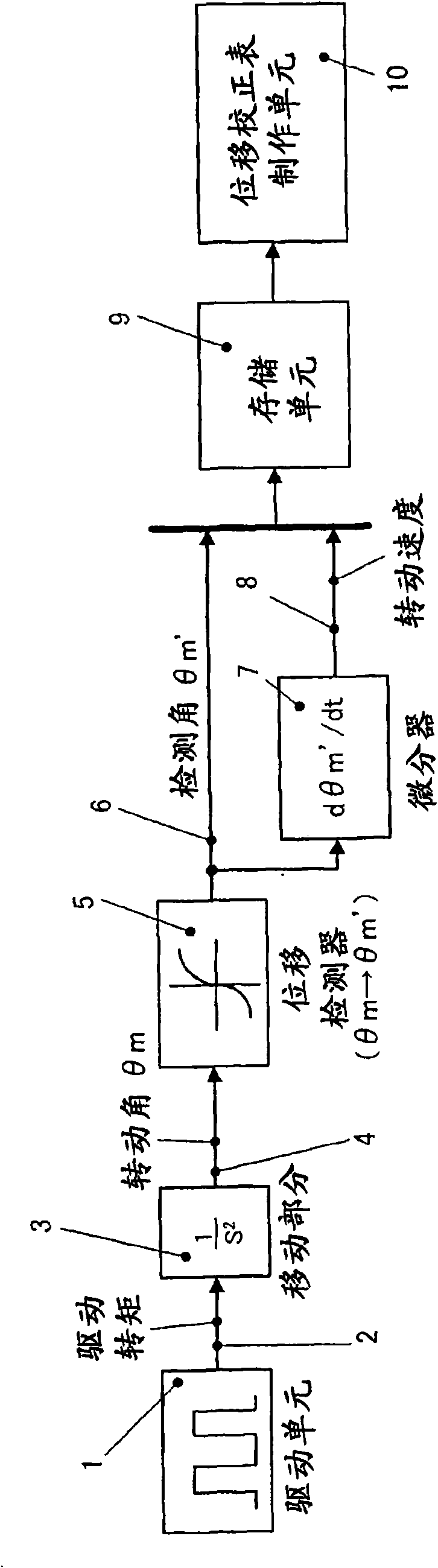
[0056] Next, the displacement detection method and the motor control apparatus in Embodiment 1 of the present invention will be described. figure 1 is a block diagram of the control performed by the motor control device.
[0057] figure 1 The control block in is a positioning control system in which a rotary encoder is used as an angle detector for detecting the rotation angle θm of the motor. exist figure 1 In , a simple model of the moving part is shown in which the position response to a torque command is 1 / s 2 .
Login to View More PUM
 Abstract
The invention relates to a displacement detecting method, a correction table making method, a motor control apparatus, and a processing machine. The displacement detecting method of the present invention includes the steps of driving a moving part (3) using a drive unit (1), detecting a displacement amount (6) (detected angle m') of the moving part (3) using a displacement detector (5), correcting the displacement amount (6) (detected angle theta m') using a displacement correction table so that a displacement velocity (d m' / dt) of the displacement amount (6) (detected angle theta m') detected by the displacement detector (5) is constant, and detecting a displacement amount (detected angle theta m'') corrected by the displacement correction table as the displacement amount of the moving part (3).
Description
technical field [0001] The present invention relates to a displacement detection method for correcting displacement information to improve detection accuracy, a correction table preparation method, a motor control device, and a processing machine. Background technique [0002] The applicant of the present application is developing a galvano motor for processing machines such as laser processing machines, laser trimmers, and laser repair machines. For current motors, an incremental encoder (incremental encoder) is used as a high-precision angle detector. The applicant is considering a means of electric division of the encoder signal. [0003] Conventionally, electrical division has been performed based on the premise that two-phase analog sine-wave and cosine-wave signals that have the same amplitude and offset value and are out of phase with each other by 90 degrees are output. Electrical division may be performed after correcting the output signal from the encoder so that...
Claims
Login to View More Application Information
Patent Timeline
 Patent Type & AuthorityApplications(China)
IPC IPC(8): G01D5/347G01D5/245H02P6/16B23K26/00G02B26/08H02P29/00
CPCG01D5/24476B23K26/08B23K26/0807G05B19/408B23K26/041G01D5/2448B23K26/20B23K26/082B23K26/042B23K26/21G01B7/00G01B11/00
Inventor上田伸治
OwnerCANON KK