Configuration designing method for structure under inertial load effect

A technology of inertial load and design method, applied in calculation, special data processing applications, instruments, etc., can solve problems such as poor stiffness, and achieve the effect of improving stiffness

Inactive Publication Date: 2009-12-16
NORTHWESTERN POLYTECHNICAL UNIV
View PDF0 Cites 9 Cited by
  • Summary
  • Abstract
  • Description
  • Claims
  • Application Information

AI Technical Summary

Problems solved by technology

[0012] In order to overcome the deficiency of poor rigidity in the structural configuration design results of the prior art, the present invention provides a structural configuration design method under the action of inertial load, which adopts the material interpolation model method and the corresponding math...

Method used


Image

  • Configuration designing method for structure under inertial load effect
  • Configuration designing method for structure under inertial load effect
  • Configuration designing method for structure under inertial load effect

Examples


Embodiment 1

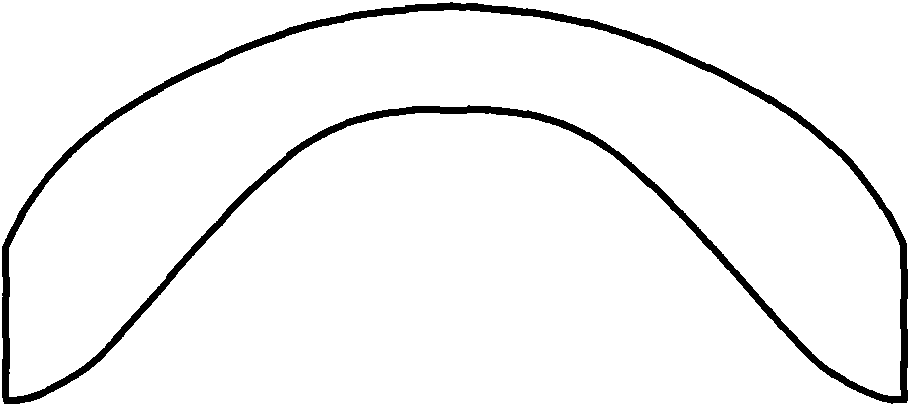
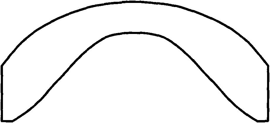
[0041]Example 1: (1) Divide a rectangular plane structure with a length and width of 10cm and 5cm into a square grid of 80×40; both ends of the bottom of the structure are fixed, and only the gravity of the structure, that is, the inertial overload a in the vertical direction, is considered =9.8m / s 2 ;Given vf=0.4, the solid material is steel (ie ρ 0 =7800kg / m 3 ,E 0 =210GPa); given sensitivity filter radius r F = 0.2 cm. When using the progressive structure optimization method, RR=0.01 and GR=0.002 are given.

[0042] (2) According to the current design variable value and the parameters set in step (1), given R=16, the material density ρ of each finite element unit is calculated by linear and RAMP (Rational Approximation of Material Properties) material interpolation models respectively i and Young's modulus E i , update the corresponding material properties in the structural finite element model and perform structural finite element analysis; the calculation formul...

Embodiment 2

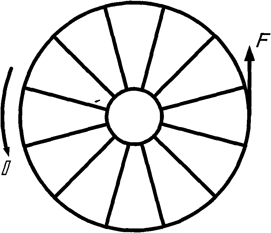
[0058] Example 2: (1) The planar annular circular symmetric structure is divided into 12 unit cells along the circumferential direction, that is, the 12 unit cells always have the same configuration; the inner and outer circumference radii are 10cm and 30cm respectively, and the entire ring is divided into 240 The finite element mesh of ×40; assuming that all the inner circumferences are fixed, the load is a tangential concentrated load F=50kN acting on the symmetric axis of a certain unit cell, and the structure rotates at a constant speed of 500r / min around the axis (that is, the angular velocity ω=52.36rad / s) produced centrifugal force; given vf=0.4, the solid material is aluminum (ie ρ 0 =2700kg / m 3 ,E 0 =70GPa); given sensitivity filter radius r F = 0.8 cm.

[0059] (2) According to the current design variable value and the parameters set in step (1), given R=8, the material density ρ of each finite element unit is calculated by linear and RAMP (Rational Approxi...


PUM


Abstract

The invention discloses a configuration designing method for structure under inertial load effect, which is characterized in that a linear model and a RAMP interpolation model are respectively adopted for material density and Young modulus. The method takes integral stiffness maximum (namely softness minimum) of a structure as the goal and the volume of a given material as restriction and utilizes a mathematical programming method or a progressive structural optimization method to carry out the configuration designing for structure under inertial load effect. In each optimization design iteration, sensitivity filtration is carried out after objective function sensitivity is obtained by calculation. The invention has the beneficial effects that the coincident designing result is obtained by using the mathematical programming method and the progressive structural optimization method, and the integral stiffness of the structure under the inertial load effect is increased compared with the designing result of the existing business software.

Description

technical field [0001] The invention relates to a structural configuration design method, in particular to a structural configuration design method under the action of inertial load. Background technique [0002] Inertial load is a body load that is directly related to the structural mass generated under the action of acceleration, so the inertial load is directly related to the presence or absence of materials. According to different forms of acceleration, it can be divided into two types: inertial overload (including the structure's own weight) generated by linear acceleration and centrifugal force generated under the action of rotational angular velocity. The optimal design of structures under inertial loads has important theoretical and practical value. [0003] There are two main methods for structural configuration optimization design under inertial loads: mathematical programming method and progressive structural optimization method. In the mathematical programming ...

Claims


Application Information

Patent Timeline
IPC IPC(8): G06F17/50
Inventor 张卫红高彤
Owner NORTHWESTERN POLYTECHNICAL UNIV
Why Eureka
Try Eureka