Material microstructure image-based method for automatic mesoscale crack statistics
A technology of microstructure and statistical methods, which is applied in the direction of analyzing materials, using wave/particle radiation for material analysis, calculation, etc., and can solve problems affecting the accuracy of quantitative statistics of cracks, etc.
- Summary
- Abstract
- Description
- Claims
- Application Information
AI Technical Summary
Problems solved by technology
Method used
Image
Examples
Embodiment 1
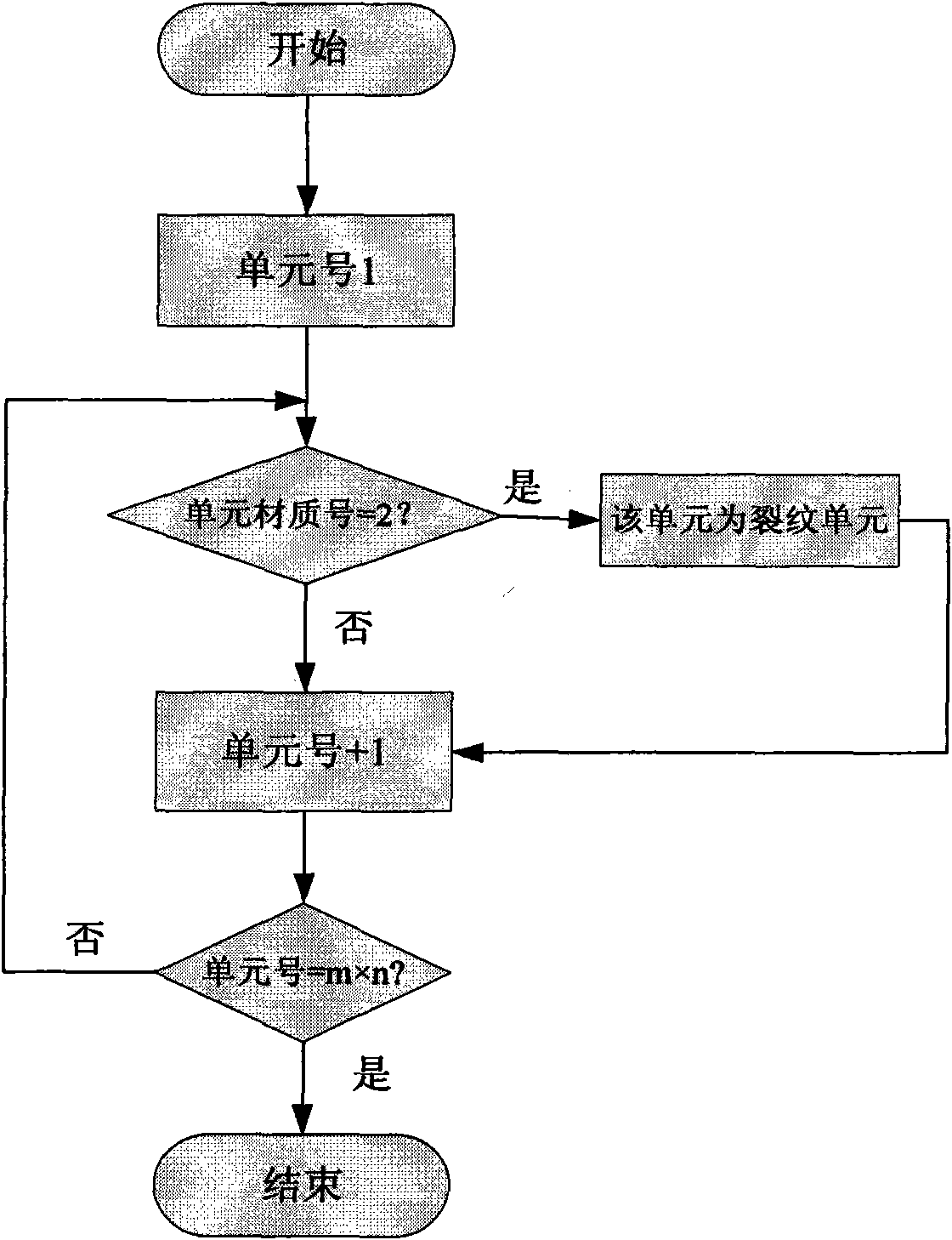
[0032] Read in the microstructure pictures of zirconia coating with a magnification of 500, a resolution of 150×150, and a node unit length scale value of 5 = 0.2 μm through programs such as MATLAB, such as Figure 4 shown. Firstly, the image is gray-scale processed to obtain a gray-scale matrix and imported into the finite element software to generate a finite element model with 22,500 finite element grid cells. And set the material number of the initial crack as 2 and the material number of the matrix as 1 through programs such as ANSYS APDL. in The color represents the base material of the coating, Colors represent cracks in the coating. Such as Figure 5 shown.
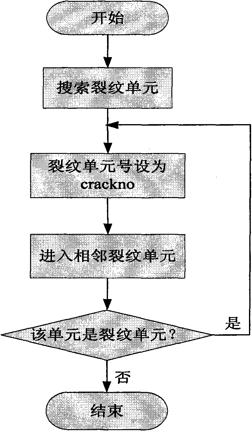
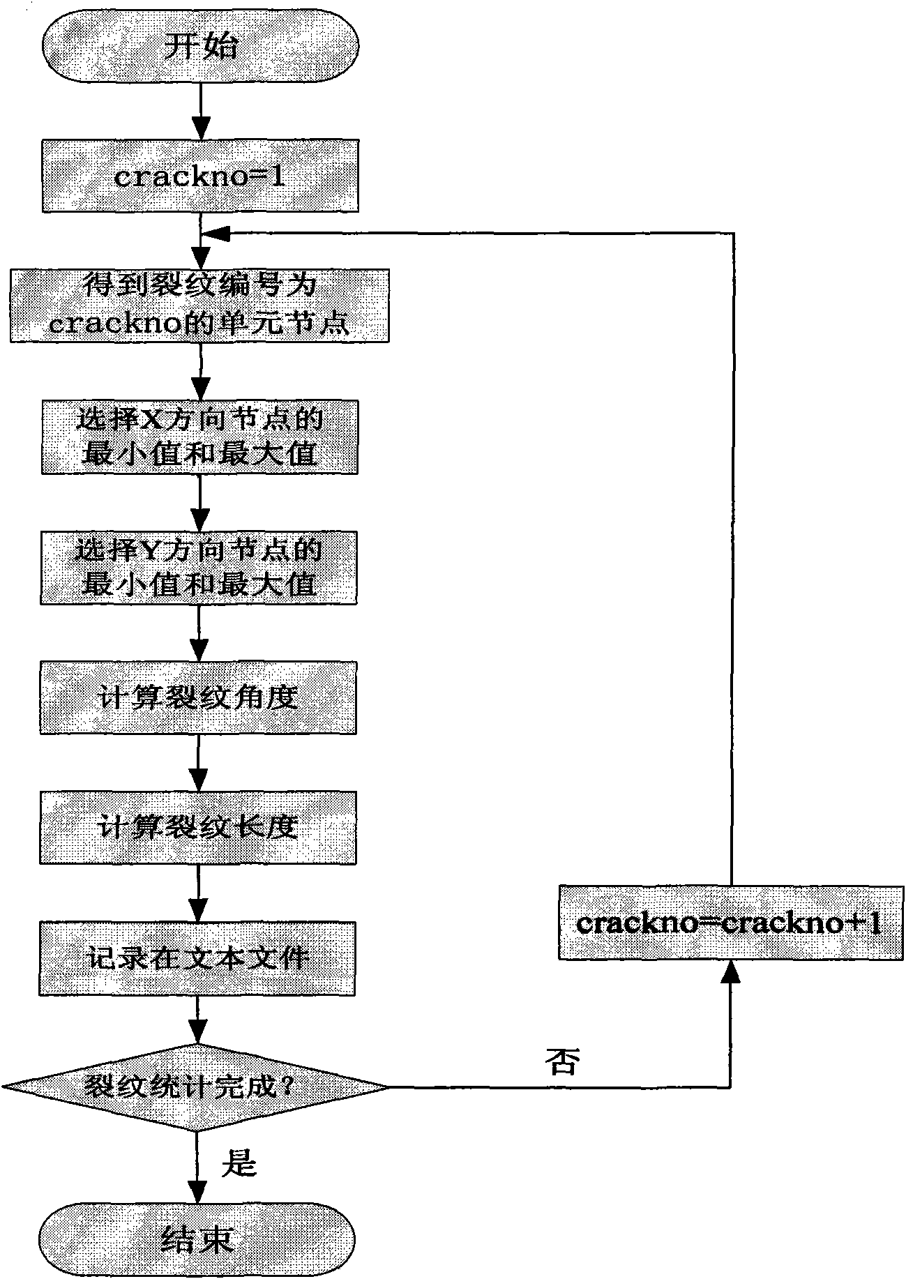
[0033] According to the generated finite element grid, the initial crack number crackno=1 is preset, and the cycle starts from unit number 1 to the last unit number 22500 to search for crack units. When the unit with material number 2 is reached, it is considered to have reached the crack unit. At the first...
Embodiment 2
[0036] Read in the microstructure pictures of zirconia coating with a magnification of 500 and a resolution of 200×200 node unit length scale value δ=0.2 μm through programs such as MATLAB, such as Figure 6 shown. The image was grayscale processed to obtain a grayscale matrix and imported into the finite element software to generate a finite element model with 40,000 finite element mesh units. And set the material number of the initial crack as 2 and the material number of the matrix as 1 through programs such as ANSYS APDL. in The color represents the base material of the coating, Colors represent cracks in the coating. Such as Figure 7 shown.
[0037] According to the generated finite element grid, the initial crack number crackno=1 is preset, and the cycle starts from unit number 1 to the last unit number 40000 to search for crack units. When the unit with material number 2 is reached, it is considered to have reached the crack unit. At the first cracked element ...
Embodiment 3
[0040] Read in the microstructure pictures of zirconia coating with a magnification of 1000 and a resolution of 200×180 node unit length scale value δ=0.1 μm through programs such as MATLAB, such as Figure 8 shown. The image is grayscale processed to obtain a grayscale matrix and imported into the finite element software to generate a finite element model with 36,000 finite element grid cells. And set the material number of the initial crack as 2 and the material number of the matrix as 1 through programs such as ANSYS APDL. in The color represents the base material of the coating, Colors represent cracks in the coating. Such as Figure 9 shown.
[0041] According to the generated finite element grid, the initial crack number crackno=1 is preset, and the cycle starts from unit number 1 to the last unit number 36000 to search for crack units. When the unit with material number 2 is reached, it is considered to have reached the crack unit. At the first cracked element ...
PUM
| Property | Measurement | Unit |
|---|---|---|
| length | aaaaa | aaaaa |
| angle | aaaaa | aaaaa |
| length | aaaaa | aaaaa |
Abstract
Description
Claims
Application Information
 - R&D
- Intellectual Property
- Life Sciences
- Materials
- Tech Scout
- Unparalleled Data Quality
- Higher Quality Content
- 60% Fewer Hallucinations
Browse by: Latest US Patents, China's latest patents, Technical Efficacy Thesaurus, Application Domain, Technology Topic, Popular Technical Reports.
© 2025 PatSnap. All rights reserved.Legal|Privacy policy|Modern Slavery Act Transparency Statement|Sitemap|About US| Contact US: help@patsnap.com


