
Pneumatic tire

A technology of pneumatic tires and tires, which is applied to the reinforcement layer, tire parts, tire edges and other directions of pneumatic tires, can solve problems such as failure and breakage, and achieve the effect of inhibiting the deterioration of riding comfort and improving durability.

Inactive Publication Date: 2009-12-16
BRIDGESTONE CORP
View PDF1 Cites 4 Cited by
  • Summary
  • Abstract
  • Description
  • Claims
  • Application Information

AI Technical Summary

Problems solved by technology

[0005] However, in a conventional tire having a structure in which a reinforcing layer is disposed outside the carcass ply, the so-called flex zone (flex zone) corresponding to the upper portion of the folded carcass ply end ( Figure 5 The part surrounded by a circle in the middle), there is a case where a part of the cord of the reinforcement layer breaks and causes a failure, which becomes a problem

Method used


Image

  • Pneumatic tire
  • Pneumatic tire
  • Pneumatic tire

Examples


Embodiment 1

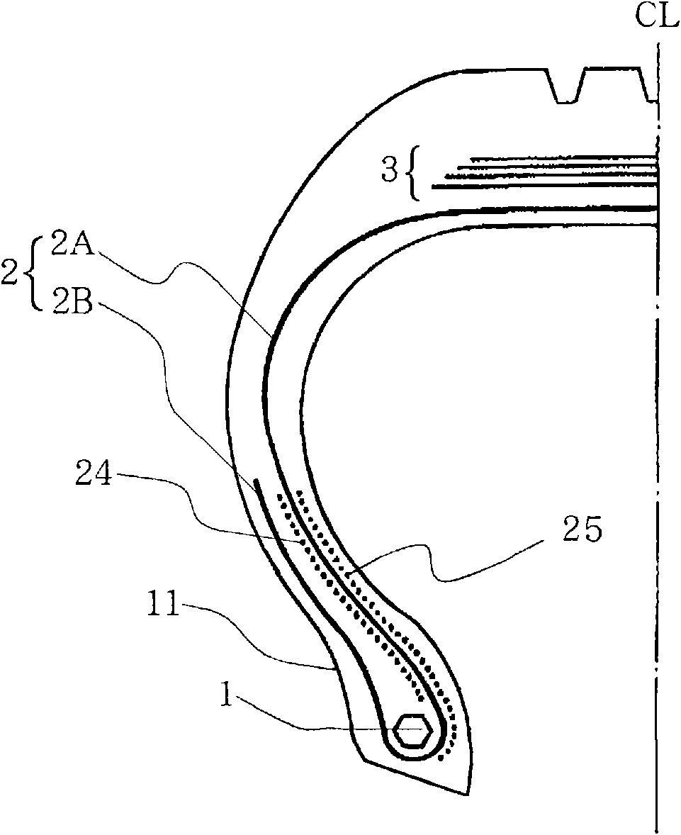
[0039] Such as image 3 The pneumatic tire shown includes a steel wire radial carcass layer 2 and four steel belt belt layers 3 arranged on the outer side of the steel wire radial carcass layer 2 in the tire radial direction, and the above one steel wire radial carcass layer 2 is folded back from the inside to the outside around the bead cores 1 embedded in the pair of bead parts 11 and locked, and is composed of main parts 2A and 2B, and the main part 2A extends in a ring shape between the bead cores 1 The above-mentioned folded portion 2B is provided continuously with the main body portion, and is folded around the bead core 1, and the outer sidewall reinforcement is respectively arranged on the outer side and the inner side of the main body portion 2A of the carcass layer in accordance with the conditions described in Table 1 below. layer 24 and the inner sidewall reinforcing layer 25 to manufacture the pneumatic tire of Example 1.

Embodiment 2

[0041] Such as Figure 4 As shown, the pneumatic tire of Example 2 was produced in the same manner as in Example 1 except that the arrangement positions of the outer side reinforcing layer 34 and the inner side reinforcing layer 35 were changed under the conditions shown in Table 1 below. In addition, the inner sidewall reinforcing layer 35 in this case is separately arranged.

Embodiment 3

[0043] The arrangement conditions of the inner sidewall reinforcing layer 25 were the same as those of Example 1 except that Table 1 below was changed, and a pneumatic tire of Example 3 was manufactured.

[0044] Conventional Example 1

[0045] A pneumatic tire (not shown) of Conventional Example 1 was produced in the same manner as in Example 1 except that the outer side reinforcing layer and the inner side reinforcing layer were not provided.

[0046] Conventional example 2

[0047] Such as Figure 5 As shown, the pneumatic tire of Conventional Example 2 was produced in the same manner as in Example 1, except that only the outer side reinforcing layer 44 was provided and the inner side reinforcing layer was not provided. In addition, reference numeral 45 in the figure denotes a bead portion reinforcing layer.

[0048] Table 1

[0049]


PUM


Abstract

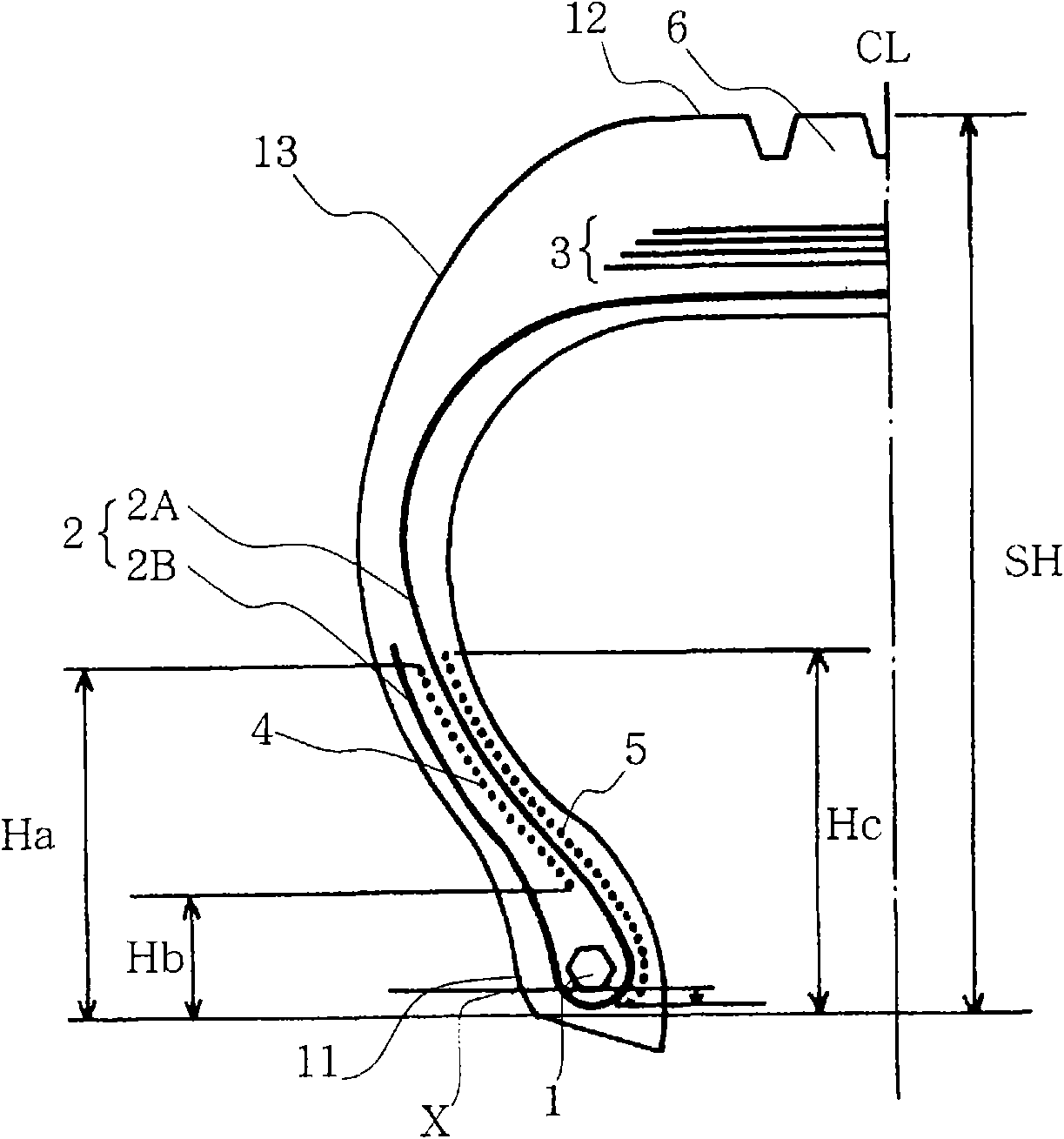
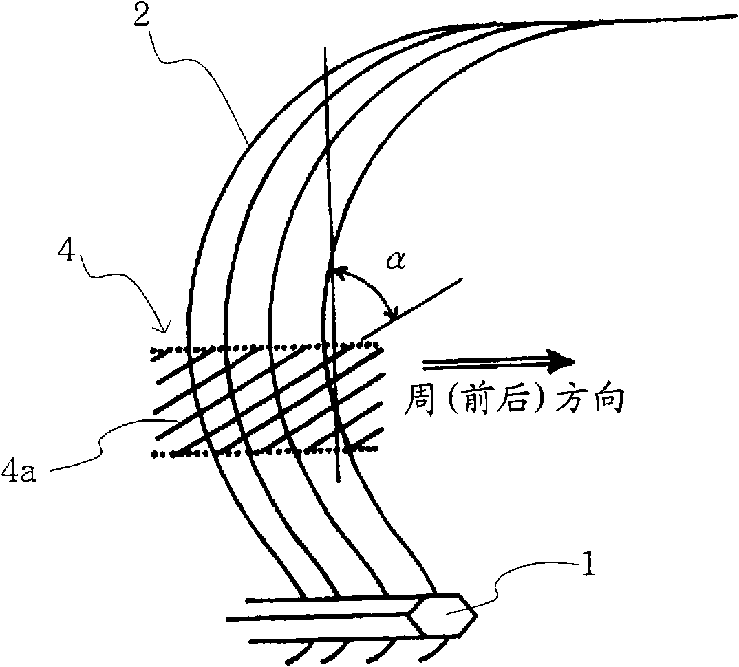
A pneumatic tire simultaneously achieving enhanced durability of reinforcement layers and increased stability of the vehicle with degradation of riding comfort of the vehicle prevented, or more particularly, a heavy duty pneumatic tire suitable for use in construction vehicles etc. The pneumatic tire has a carcass (2) constructed from a body section (2A) toroidally extending between bead cores and turned back portions (2B) continuously provided with the body section (2A) and turned back around bead cores, and the pneumatic tire also has belts (3) placed on the outside in the tire's radial direction of the carcass (2). On the outside, on each side in the axial direction of the tire, of the body section (2A) of the carcass, there is provided an outer side-reinforcement layer (4) extending along the body section, from a position that is 42% - 48% of the tire's cross-sectional height SH to a position that is 10% - 16% of the tire's cross-sectional height SH. Also, on the inside, on each side in the axial direction of the tire, of the body section (2A) of the carcass, there is provided an inner side-reinforcement layer (5) extending along the body section, from a position that is 42% - 48% of the tire's cross-sectional height SH to a position below the bottom face of the bead core.

Description

technical field [0001] The present invention relates to a pneumatic tire (hereinafter simply referred to as a "tyre"), and more specifically to a heavy-duty pneumatic tire used for construction vehicles and the like. Background technique [0002] Conventionally, in heavy-duty pneumatic tires used for construction vehicles and the like, for example, when carrying out operations such as up and down and moving loads when mounted on a construction vehicle, there has been a problem that the vehicle shakes and the workability deteriorates. [0003] In this regard, stability is improved by providing a reinforcing layer outside the carcass layer constituting the tire frame. The inner side is equipped with a predetermined reinforcement layer, and when it is installed on a construction vehicle or the like, the stability of the vehicle is improved without reducing the ride comfort. [0004] Patent Document 1: Japanese Patent Laid-Open No. 2005-313764 (Claims, etc.) [0005] However, ...

Claims


Application Information

Patent Timeline
Patent Type & Authority Applications(China)
IPC IPC(8): B60C13/00B60C15/06
CPCB60C15/06B60C9/09B60C2015/0639Y10T152/10864
Inventor 福岛将治
Owner BRIDGESTONE CORP
Learn More